* Product Parameters
Operating frequency:10kHz-500KHz Operating temperature:-40℃ to +125℃ Storage temperature:-25℃ to +85℃ Storage humidity:30 to 95%
* Features
The EE55 transformer is a classic platform designed for medium-to-high power, high-frequency switching power supply applications. Its core feature lies in its standardized, large-size ferrite core, combined with flexible air gap and winding design, enabling efficient and compact high-energy conversion and transmission at high switching frequencies.
* Typical application areas Power supply and energy sector Consumer and commercial electronics Special and industrial equipment field Power electronics and drive fields
* Product Standards UL, RoHS, 3C,CQC
* Size Specifications 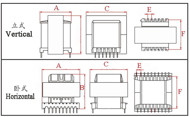
Type | Structure
Tурe | Dimension(mm) | Pin Row (mm) | Row Pitch(mm) | OD Pin(mm) | note | A | B | C | Pin | E | F | EE55-001 | Vertical | 44.0 | 57.0 | 53 | 7+7 | 5 | 39.4 | Φ1.0 |
| EE55-002 | Horizontal | 57.0 | 57.0 | 44 | 7+7 | 5 | 40 | Φ1.0 |
| EE55-003 | Horizontal | 57.0 | 57.0 | 52 | 10+10 | 5 | 45 | Φ1.0 |
| EE55-004 | Horizontal | 57.0 | 57.0 | 70 | 10+10 | 5 | 45 | Φ1.0 |
| EE55-005 | Horizontal | 57.0 | 57.0 | 41 | 11+11 | 5 | 40 | Φ1.0 |
| EE55-006 | Vertical | 56.0 | 50.0 | 58 | No pin | 6 | 0 |
|
|
*The above are commonly used skeleton styles for the company.,Other styles are not included.,Inquiries are welcome. Our company can customize various specifications according to customer requirements.High-frequency transformer.
EE55 Transformer (External Span A=55mm) is a 1200–3000W high-frequency, high-power platform. Characterized by high power density, low loss, high insulation, and wide-temperature stability, it is suitable for demanding application scenarios in industrial, energy storage, and new energy fields. The following analysis covers its core electrical performance, quantitative specifications, topology compatibility, and key optimization points. I. Core Electrical Performance & Quantitative Specifications (Baseline: PC44 Ferrite, 100kHz) Performance Dimension | Key Parameter | Typical Range | Engineering Significance | Power Handling | Rated Power | 1200–2000W (Natural Convection); 2000–3000W (Forced Air / Water Cooling) | Large window area supports large wire diameter/multi-strand wires, resulting in low copper loss. | Frequency Adaptation | Operating Frequency | 20kHz–500kHz (Recommended 40–200kHz) | High-frequency, low-loss operation, compatible with efficient topologies like LLC / Full-Bridge. | Efficiency & Loss | Full-Load Efficiency | LLC Topology 98.5%–99.2%; Forward / Full-Bridge 97%–98% | Low core loss (~180mW/cm³ @100kHz/200mT), controllable copper loss. | Leakage Inductance & Coupling | Leakage Inductance | ≤0.2% of Inductance (Can be ≤0.08% with optimized winding) | Symmetrical shell-type magnetic path + interleaved winding suppresses EMI, improves dynamic response. | Insulation & Isolation | Isolation Withstand Voltage | Primary-Secondary: 15–43kV AC/1min; Winding-Core: 1.5–2kV AC/1min | Meets UL60601/UL508C, suitable for medical/industrial applications requiring high insulation. | Leakage Current | ≤10μA | Ensures personnel safety, complies with medical equipment leakage current standards. | Inductance & DCR | Inductance Tolerance | ±10%–±15%; Primary DCR ≤200mΩ, Secondary DCR ≤30mΩ | Low internal resistance reduces voltage drop, improves load regulation. | Load Regulation | ≤0.8% | Stable output, suitable for precision instruments and industrial control. | Thermal Performance | Insulation Class | Class B (130℃) / Class F (155℃); Full-Load Temp. Rise ≤35K | Stable across wide temperature (-40℃~+125℃), suitable for enclosed spaces. | Saturation & Air Gap | Saturation Flux Density | Bs≈420–460mT; Air Gap 3.5–6.5mm | Prevents saturation, suitable for high current and short-term overload (200%–300%). |
II. Detailed Explanation of Core Electrical Performance Power & Loss Characteristics
The power range is determined by the core's effective cross-sectional area (Aₑ) and window area. Compared to the EE42, the EE55 has an Aₑ over 25% larger and a window area over 20% larger, enabling it to handle higher current and power.
Core material selection (N97/PC44) reduces high-frequency core loss. Windings using multi-strand Litz wire / copper foil minimize skin and proximity effects, significantly lowering copper loss. The overall low loss contributes to improved efficiency.
Electromagnetic Coupling & Leakage Inductance Control
The symmetrical EE structure provides a uniform magnetic path, achieving a coupling coefficient ≥0.998 and extremely low leakage inductance. This reduces voltage spikes and EMI interference, easing snubber circuit design.
Interleaved layered winding + copper foil shielding can further reduce leakage inductance, making it suitable for EMI-sensitive applications like medical and communication equipment.
Insulation & Safety Performance
Creepage distance ≥28mm meets high isolation requirements, and strict leakage current control suits medical equipment and industrial high-voltage scenarios.
Insulation resistance ≥10⁴ MΩ @500VDC ensures resistance to moisture and aging, enhancing long-term reliability.
Thermal & Stability Performance
Efficient heat dissipation design (bobbin with heatsink / forced air cooling) lowers temperature rise and extends lifespan.
Minimal parameter drift across a wide temperature range makes it suitable for harsh environments like outdoor and automotive applications.
III. Topology Compatibility & Performance Optimization Topology Type | Suitable Power Range | Core Advantage | Optimization Suggestion | LLC Resonant | 1500–3000W | Soft switching, efficiency >98.5%, low EMI | Air gap 4.5–6mm, precise inductance control, enhances resonant efficiency. | Full-Bridge | 1800–3000W | High power handling, low loss | Use layered/interleaved winding, keep leakage inductance ≤0.1% to suppress switching loss. | Forward | 1200–1800W | Low output ripple, simple control | Ideal for medical devices; reinforce insulation and leakage current control. | Half-Bridge | 1200–1500W | Low cost, simple structure | Suitable for industrial power supplies; optimize DCR and load regulation. |
EE55 Ferrite Core Transformer The EE55 ferrite core transformer is a classic and widely used core in the field of power electronics, especially in medium to high-power switch-mode power supplies. Its characteristics are mainly reflected in the following aspects: I. Core Structural Characteristics (EE Type) Standard E-Type Structure:
Composed of two symmetrical "E"-shaped ferrite cores assembled together, with the magnetic path adjusted via an air gap spacer in between. This structure is mature, versatile, and has a simple manufacturing process.
The coil is wound on the center leg. The magnetic path is closed, resulting in relatively low magnetic leakage, making electromagnetic interference easier to control.
Standardized Dimensions:
The "55" denotes the core size, typically referring to a center leg width of approximately 55mm (specific dimensions should be verified against the corresponding manufacturer's datasheet, such as TDK, Ferroxcube, etc.).
It belongs to the medium-to-large core category, possessing a relatively large effective cross-sectional area and window area.
II. Electrical & Performance Characteristics High Power Capacity:
Due to its larger size, the EE55 core can handle higher power levels, typically suitable for applications ranging from several hundred watts to over two kilowatts, such as in switch-mode power supplies, inverters, and photovoltaic/energy storage converters.
The large window area allows for the use of thicker copper wire or multiple parallel strands to carry high current, thereby reducing copper loss.
High Operating Frequency:
Utilizing manganese-zinc power ferrite materials (e.g., PC40, PC44, PC95, etc.), its optimal operating frequency typically ranges from tens of kHz to several hundred kHz. This is significantly higher than silicon steel laminated cores, enabling transformers to be made smaller and lighter.
Flexible Air Gap Design:
The assembled structure facilitates the addition of an air gap on the center leg or side legs.
Key Role: The air gap can significantly increase the core's energy storage capacity and prevent saturation under DC bias, making it an essential design feature for energy-storage magnetic components like flyback transformers and PFC inductors.
The air gap size must be precisely calculated and adjusted to achieve the correct inductance.
Good Thermal Performance: High Customizability of Parameters:
Winding parameters such as number of turns, wire gauge, winding technique (e.g., sectional winding to reduce parasitic capacitance), and winding sequence (e.g., interleaving primary and secondary to reduce leakage inductance) can all be flexibly designed according to the specific circuit topology (Forward, Flyback, Half-Bridge, Full-Bridge, etc.) and performance requirements.
III. Application Domain Characteristics
Widely used in switch-mode power supplies: An ideal choice for main transformers and PFC inductors in medium-to-high-power AC-DC and DC-DC switch-mode power supplies.
New Energy and Industrial Fields: Commonly found in equipment such as solar inverters, UPS systems, telecommunications power supplies, welding machines, and industrial motor drives.
Suitable for Various Topologies:
Flyback Topology: Used as a transformer for energy storage and transfer, requiring an air gap.
Forward, Bridge Topologies: Used as a pure transformer, typically not requiring a large air gap or needing only a minimal one.
Inductor: With a designed air gap, it can be directly used as a high-power filter inductor or PFC boost inductor.
IV. Summary of Advantages and Disadvantages Advantages:
High Power Density: Achieves high-power transfer at elevated frequencies, with superior size and weight compared to silicon steel laminated cores.
Good Cost-Effectiveness: Mature structure with relatively controllable material and manufacturing costs, offering a high cost-performance ratio.
High Versatility: Industry-standard size, easy to procure, with abundant design resources available.
Good Thermal and Manufacturing Performance: Easy to wind, assemble, and manage for heat dissipation.
Disadvantages / Considerations:
Brittle Material: Ferrite cores are relatively brittle and require care during installation and transport to prevent cracking from mechanical stress.
Temperature Sensitivity: Ferrite permeability varies with temperature. The Curie point is typically 200-250°C. Designs must ensure sufficient margin at the maximum operating temperature.
Requires Precise Design: Parameters like air gap and winding details significantly impact performance. Rigorous calculation and optimization are needed based on operating frequency, flux density, temperature rise, etc.
High-Frequency Losses: At very high frequencies (e.g., MHz and above), ferrite losses increase sharply. In such cases, other materials (e.g., alloy powder cores) may need to be considered.
EE55 Transformer (Transformers based on the EE55 core), with their medium-to-high power handling capability, excellent high-frequency performance, and mature manufacturing process, play a pivotal role in numerous fields requiring efficient power conversion. Their applications are extensive, primarily concentrated in the following key industries: I. Power Supply & Energy Sector (Core Application) This is the most classic and widely-used domain for EE55 transformers.
Industrial and Telecommunications Switching Power Supplies:
Medium-to-High Power AC-DC Power Supplies: Provide stable DC power for industrial control equipment, testing instruments, automated machinery, etc., typically in the power range of 300W to 1500W.
Communication System Power Supplies: Used in the 48V DC power distribution systems of equipment such as base stations, data centers, routers/switches (e.g., isolated DC-DC modules like 48V to 12V, 48V to 5V), requiring high reliability and efficiency.
Server Power Supplies: In modern high-density server power supply units (PSUs), the EE55 is commonly used as the main transformer in LLC resonant topologies, handling kilowatt-level power and pursuing extremely high conversion efficiency (e.g., Titanium, Platinum level).
New Energy Generation and Energy Storage:
Photovoltaic (PV) Inverters: Used in string or micro-inverters for front-end boost (DC-DC) or rear-end isolated inversion (DC-AC) stages, processing DC power from solar panels.
Energy Storage Converters (PCS): In battery energy storage systems, enabling bidirectional energy conversion between batteries and the grid (AC-DC and isolated DC-DC). The EE55 is suitable for the isolated DC-DC conversion stage within this process.
Electric Vehicle Charging Modules: Inside the power modules of AC slow or DC fast charging piles, serving as high-frequency isolation transformers to ensure safety and improve efficiency.
II. Consumer and Commercial Electronics As power density requirements increase, the EE55 has also entered higher-end consumer markets. III. Specialized and Industrial Equipment These fields place extremely high demands on transformer reliability, robustness, and environmental adaptability.
Medical Equipment Power Supplies:
High-end medical imaging equipment (e.g., CT, X-ray machines), analytical instruments, and surgical equipment require exceptionally stable, low-noise, high-isolation power supplies. The EE55 is a common choice here.
Industrial Lasers and Processing Equipment:
Welding Machines:
The core of inverter-based welding machines (IGBT/MOSFET welders) involves converting mains AC power through high-frequency switching and transformers like the EE55 into high-current, low-voltage output, achieving weight and size reduction.
Uninterruptible Power Supplies (UPS):
In online UPS systems, EE55 transformers may be used in the AC-DC rectification stage, DC-AC inversion stage, or the DC-DC stage for battery charging/discharging to achieve electrical isolation and voltage transformation.
IV. Power Electronics and Drive Systems Here, the EE55 serves as a key component for energy transfer and isolation.
|


