* Product Parameters Operating frequency: 20kHz ~ 500kHz, suitable for high-frequency switching power supplies. Output power: 10W ~ 1000W, depending on the operating frequency and core material. Operating temperature: -40℃ ~ +125℃ (some models can reach +180℃). Storage conditions: -25℃ ~ +85℃, humidity 30% ~ 95% RH. Insulation withstand voltage: Usually requires AC 2000V, insulation resistance ≥200MΩ (tested at DC 500V).
* Product Features The core feature of the PQ transformer is that it achieves an almost perfect balance between the excellent electrical performance (low leakage inductance, easy winding) brought by the "round center post" and the excellent mechanical and heat dissipation characteristics provided by the "square outer edge".It has the characteristics of high operating frequency, high efficiency, small size, and light weight..
* Typical Application Areas Main transformer for switching power supplies: Compatible with 50 - 500kHz high-frequency switching power supplies to provide stable voltage conversion. Communication power supplies: Meet the high requirements of communication equipment for power density, anti-interference, and efficiency. Industrial control power supplies: Compatible with high-frequency working conditions to ensure stable power supply for the control system. High-power chargers: Utilize the power density advantage of PQ2020 to achieve miniaturized and efficient charging.
* Product Standards UL, RoHS, 3C, CQC * Dimensions and Specifications 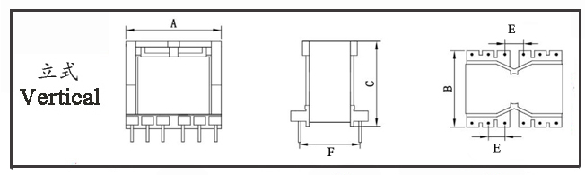
Model | Structure Type | Dimensions (mm) | Number of Pins | Pin Pitch (mm) | Row Pitch (mm) | Pin Diameter
mm | Remarks | A | B | C | Pin | E | F | PQ20 - 001 | Vertical | 23.0 | 23.0 | 18.5 | 6+8 | 3.8/2.5/5.0 | 20.50 | Φ0.6 |
| PQ20 - 002 | Vertical | 21.0 | 21.0 | 21.0 | 6+6 | 3.5/4.3 | 19.00 | Φ0.7 |
| PQ20 - 003 | Vertical | 23.0 | 23.0 | 22.5 | 6+6 | 3.8/5.0 | 20.50 | Φ0.6 |
| PQ20 - 004 | Vertical | 21.0 | 21.0 | 21.0 | 6+6 | 3.5/4.3 | 19.00 | Φ0.7 |
|
The above are the commonly used bobbin styles of the company.,Other styles are not listed for the time being.,Welcome to consult. Our company can customize high - frequency transformers of various specifications according to customer requirements.
PQ2020 High-Frequency Transformer The "20" in the model number indicates an A dimension of 20mm. It utilizes a PQ-type ferrite core, featuring a compact structure, high power density, and low loss. It is widely used in medium- and low-power switching power supplies.
I. Dimensions and Structure
Overall Dimensions: Typical dimensions are approximately 24mm × 24mm × 22mm (L × W × H). It adopts a vertical mounting design, saving PCB space.
Pin Configuration: Commonly features a 6+8 pin layout with a pitch of approximately 20.5mm, facilitating multi-winding designs.
II. Key Electrical Performance Analysis1. Inductance Characteristics
Magnetizing Inductance (Lm): Reflects the core's energy storage capability. It is proportional to the square of the number of turns and the effective core cross-sectional area (Ae) and inversely proportional to the magnetic path length (Le). The decrease in permeability at high frequencies must be considered.
Leakage Inductance (Lk): Generated by non-coupled magnetic flux. The PQ2020 structural design effectively reduces leakage inductance, typically requiring it to be below 40μH to minimize switching losses and EMI interference.
Distributed Capacitance: Inter-winding and inter-layer capacitance can easily cause resonance at high frequencies. Optimization through segmented winding or shield layer design is necessary.
2. Loss Characteristics
Core Loss (Pc): Includes eddy current losses and hysteresis losses, related to frequency, flux density, and temperature. Materials like PC40 maintain low losses even at 500kHz, ensuring efficient transformer operation.
Copper Loss (Pc): Caused by the DC resistance (DCR) and AC resistance (ACR) of windings. The skin effect at high frequencies increases ACR, requiring appropriate wire gauge and winding methods to reduce losses.
3. Insulation and Withstand Voltage
Insulation Resistance: Under normal conditions, the insulation resistance between primary and secondary windings, as well as between primary winding and core, must be ≥100MΩ to ensure reliability.
High-Potential (Hipot) Test: Between primary-secondary and primary-core windings, it must withstand 1500VAC/60s with a leakage current ≤5mA, complying with safety standards.
4. Temperature Rise and Heat Dissipation5. Anti-Interference Performance
The magnetic core structure provides good magnetic shielding, reducing electromagnetic radiation. Reasonable winding methods reduce leakage inductance and suppress differential and common-mode interference, enhancing EMC performance.
III. Performance Optimization and Application Guidelines1. Winding Design
Use the sandwich winding method (primary-secondary-primary) to reduce leakage inductance.
Implement segmented winding to minimize distributed capacitance.
Choose multi-stranded or Litz wire to mitigate high-frequency skin effects.
2. Core Selection and Treatment
Select core materials (e.g., PC40, TP4) based on operating frequency and power requirements.
When necessary, add an air gap to adjust inductance, while considering the impact of magnetic flux leakage at the gap on adjacent windings.
3. Thermal Design4. Safety and EMC Considerations
Strictly adhere to insulation distance requirements and use flame-retardant insulating materials.
Meet EMC standards through shielding and filtering measures to reduce interference with surrounding equipment.
PQ2020 Transformer The PQ2020 transformer belongs to the category of miniature high-frequency transformers. Its core design is tailored for low-power, miniaturized electronic devices. Leveraging the compact PQ-type pot core structure and specialized ferrite material, it exhibits the core characteristics of "small size, high efficiency, and strong anti-interference capability." The specific classifications are as follows:
I. Ultra-Compact Structure, Outstanding Power Density
Size Advantage: The PQ2020 transformer features a miniature PQ core specification with an optimized ratio between the core window area and effective cross-sectional area (Ae). It can achieve a power output of 3–10W (operating frequency: 200–500kHz) within an extremely small volume, perfectly meeting the demands of device miniaturization.
Easy Installation: The standardized pin pitch makes it compatible with surface-mount (SMT) or through-hole (PTH) processes on miniature PCBs. It is suitable for automated production line assembly and mass-production scenarios, reducing labor costs.
Closed Magnetic Path Design: The PQ-type pot core structure provides a fully closed magnetic path, reducing magnetic flux leakage by over 30% compared to EI cores. This minimizes electromagnetic interference with surrounding space, allowing the transformer to be placed in close proximity to other components.
II. High-Frequency, Low-Loss Operation, Ideal for Low-Power High-Frequency Applications
Material Properties: Constructed from high-permeability manganese-zinc ferrite materials (e.g., PC44, TP4), the core exhibits extremely low losses in the 200–500kHz high-frequency range. This prevents excessive temperature rise despite the small size, with a long-term operating temperature of ≤120°C.
Optimized Winding Compatibility: Supports winding with ultra-fine multi-stranded (Litz) wire, effectively reducing copper losses caused by the high-frequency skin effect. Combined with a tightly wound "primary-secondary" structure, leakage inductance can be controlled below 5µH, enhancing power conversion efficiency (no-load loss ≤0.2W).
Wide Frequency Adaptability: Can operate within a frequency range of 100–500kHz, compatible with low-power topologies such as flyback and forward converters, without requiring significant changes to the winding design.
III. Stable Electrical Performance, Strong Insulation, and Anti-Interference Capability
Reliable Insulation Safety: Withstands up to 1000VAC/60s between primary-secondary and primary-core, with leakage current ≤3mA. Under normal conditions, insulation resistance is ≥100MΩ, meeting safety requirements for consumer electronics and small-scale industrial control equipment.
Excellent Anti-Interference Performance: The pot core inherently provides magnetic shielding, resulting in far lower electromagnetic radiation compared to open-core transformers. It can meet conventional EMC standards without additional shielding covers, simplifying power circuit design.
High Parameter Consistency: The miniature core has tight dimensional tolerances. During mass production, key parameter deviations (e.g., inductance, leakage inductance) are ≤±5%, ensuring stable performance in end devices.
The PQ2020 transformer is widely used in various medium and small-power switching power supplies due to its high frequency, high power density, low loss, and excellent EMC characteristics.
Computers and Communication Equipment
Computer Power Supplies: Used in medium- and high-power switching power supplies for desktop computers, servers, and industrial equipment.
Communication Equipment: Applied in power modules for network switches, routers, base stations, and other communication devices.
Power Adapters and Charging Equipment
Laptop Power Adapters: Serves as the core component for power conversion, providing stable output.
Fast Charging Devices: Used in 60W and above USB PD fast chargers, phone chargers, and handheld switching power supply chargers.
Industrial and New Energy
Industrial Control Power Supplies: Provides power for industrial automation equipment, robots, sensor systems, etc.
New Energy Equipment: Used in auxiliary power supplies for photovoltaic inverters, internal power supplies for electric vehicle onboard chargers (OBC), etc.
Lighting and Consumer Electronics
LED Driver Power Supplies: Used in driving circuits for LED lighting, LCD backlights, etc.
Consumer Electronics: Applied in monitors, power adapters, smart home devices, etc.
Other Applications
DC-DC Converters: Functions as an energy transfer and isolation component.
UPS Systems: Used in uninterruptible power supply systems.
Inverter Power Supplies: Performs voltage transformation in inverter circuits.
|


