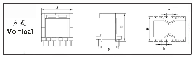
PQ transformers are high-frequency transformers using PQ type ferrite cores as their core component, known for their high power density, low loss, low leakage inductance, and excellent heat dissipation, making them suitable for compact and high-efficiency applications such as power supplies.
II. Key Performance Advantages and Principles
High Power Density:
The PQ core’s circular center pillar combined with a compact bobbin improves window utilization by 15%–20% compared to EE cores, enabling a 20%–30% increase in power output for the same volume and supporting slim-profile designs.
Low-Loss Design:
Ferrite cores (e.g., PC40/PC44) exhibit low hysteresis and eddy current losses at high frequencies, with typical losses <200 mW/cm³ at 100 kHz.
The circular center pillar reduces wire bending, lowering DC resistance and skin effect losses, resulting in 10%–15% lower copper loss compared to traditional EE cores.
Excellent Thermal Management:
The large contact area between the core and windings facilitates rapid heat transfer to the housing or substrate. The symmetrical structure ensures uniform temperature distribution, reducing full-load temperature rise by 8–12 K compared to EE cores of similar specifications.
Low EMI and High Reliability:
The closed magnetic path and symmetrical winding reduce stray flux by 30%–50% compared to EI cores, lowering the cost of EMI filtering.
Pins integrated into the bobbin ensure secure installation and high resistance to vibration, making PQ transformers suitable for harsh environments such as industrial and automotive applications.
Key Design Parameters
Operating Frequency:
25–500 kHz, with 30–200 kHz recommended for an optimal balance between losses and cost.
Topology Compatibility:
Suitable for flyback (<200 W), forward, or half-bridge (200–500 W) topologies, offering better adaptability than RM cores.
Air Gap Control:
An air gap (0.1–0.5 mm) is required in flyback topologies to prevent saturation, while forward topologies may not need one. Note that leakage inductance increases with larger air gaps.
Winding Strategy:
Primary winding split into sections, secondary winding placed centrally, and insulation between layers can reduce leakage inductance to below 0.5%.
Performance Optimization Directions
Loss Optimization:
Select low-loss cores (e.g., PC47) to reduce core losses by 25% at 100 kHz. Use multi-strand Litz wire to decrease skin effect losses by 30%.
Thermal Design:
Apply thermal grease between the core and heat sink; add cooling channels within the windings to reduce temperature rise by 10–15 K.
EMI Optimization:
Adopt a sandwich winding method (primary-secondary-primary) to reduce leakage inductance by 40%. Add a common-mode inductor in series with the primary winding to help meet EMI standards such as EN55032.