Product parameters
Operating frequency: 20kHz ~ 500kHz, suitable for high-frequency switching power supplies. Operating temperature: -40℃ ~ +125℃ (some models can reach +180℃). Storage conditions: -25℃ ~ +85℃, humidity 30% ~ 95% RH. Insulation withstand voltage: Usually requires AC 2000V, insulation resistance ≥200MΩ (tested at DC 500V).
* Product features The ETD44 transformer, with its characteristics of high efficiency, low loss, high power density, safety and reliability, has become the preferred solution for high - frequency power supply design. Through reasonable magnetic core, winding and thermal design, it can be adapted to a variety of topologies and power requirements, helping equipment achieve miniaturization, high efficiency and long service life. * Typical application fields
Communication and server power supplies: 200W - 500W LLC resonant power supplies, meeting the requirements of high efficiency and high power density, suitable for 1U/2U rack - mounted equipment. Industrial and photovoltaic inverters: 100W - 800W forward/ flyback topologies, suitable for a wide input voltage range (200V - 400V DC), with strong anti - interference ability. LED drivers and charging piles: 50W - 200W flyback topologies, suitable for constant - current output requirements, and the insulation safety margin meets outdoor and in - vehicle scenarios. Medical equipment power supplies: Class II isolation design, low leakage current (≤100μA), suitable for the safety standards of Class B medical equipment.
* Product standards UL, RoHS, 3C, CQC * Dimensions 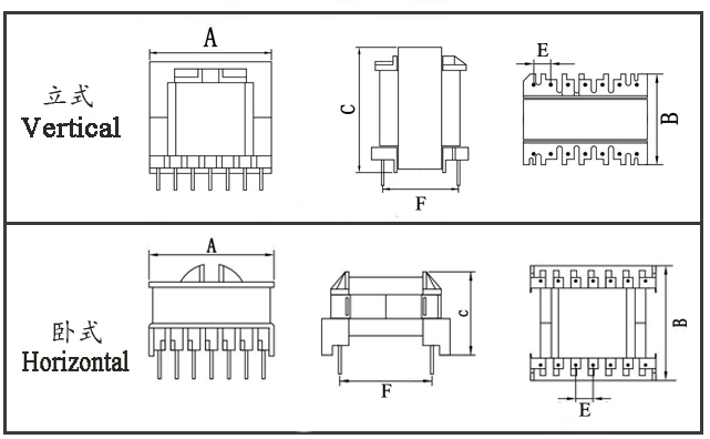
Type | Structure
Tурe | Dimension(mm) | Pin Row (mm) | Row Pitch
(mm) | OD Pin
(mm) | note | A | B | C | Pin | Pin Pitch | ETD44-001 | Vertical | 47.0 | 34.5 | 52.0 | 9+9 | 5.00 | 27.5 | Φ1.0 |
| ETD44-002 | Horizontal | 50.0 | 52.5 | 40.5 | 9+9 | 5.00 | 36.8 | Φ1.0 |
|
* The above are the commonly used bobbin styles of the company,Other styles are not included for the time being,Welcome to consult. Our company can customize high - frequency transformers of various specifications according to customer requirements.
ETD44 Transformer The ETD44 is a cost‑effective transformer widely used in high‑frequency switching power supplies (SMPS). Its core strengths include high power density, low loss, and generous insulation safety margins. It is suitable for a power range of 20 W to 800 W, typically operating at frequencies between 10 kHz and 500 kHz, and is extensively applied in server power supplies, photovoltaic inverters, industrial power supplies, and similar fields. Below is an analysis covering its core parameters, performance characteristics, loss mechanisms, thermal behavior, and application compatibility.
I. Core Structure and Key ParametersCore and Bobbin Basics
Core Material: Primarily manganese‑zinc ferrite (e.g., PC40/PC44/3C90), with a saturation flux density (Bs) of about 400–450 mT at 25 °C and a Curie temperature > 210 °C, meeting the requirements for high‑frequency, low‑loss operation.
Bobbin Specification: Commonly a horizontal 9+9‑pin bobbin with a pin pitch of 5.0 mm, offering creepage and clearance distances compliant with UL/EN safety standards, suitable for PCB through‑hole mounting.
Key Geometric Parameters (Typical Values):
Magnetic path length (Le) ≈ 110 mm
Effective cross‑sectional area (Ae) ≈ 280 mm²
Window area (Wa) ≈ 1200 mm² – providing ample space for large‑diameter windings and insulation design.
Electrical and Power Benchmarks Parameter | Typical Range | Remarks | Power Coverage | 20 W – 800 W | Depends on topology (flyback/forward/LLC) and frequency; LLC resonant topology can reach 250–500 W | Operating Frequency | 10 kHz – 500 kHz | Optimal range: 50 kHz – 200 kHz, balancing loss and efficiency | Insulation Withstand | AC 3000 V/60 s | Primary�secondary isolation, meeting UL 60950�1 requirements | Efficiency | ≥ 95% (full load) | High�frequency optimized design reduces copper and core losses | Operating Temperature | �40 °C to +125 °C | Compatible with ferrite core and insulation material heat resistance |
II. Core Performance AnalysisLow‑Loss and High‑Efficiency Mechanism
Core Loss: The circular center‑post design reduces the mean length per turn (MLT) of the winding by about 10–15% compared to a square post, lowering copper loss. The ferrite material is optimized for low hysteresis and eddy‑current losses at high frequencies, with typical losses < 500 mW/cm³ at 100 kHz.
Winding Loss: The wide‑window bobbin supports multiple parallel strands or large‑diameter conductors, reducing skin and proximity effect losses. Proper winding layering and shielding design suppress leakage inductance and parasitic capacitance, improving conversion efficiency.
Power Density and Topology Compatibility
Power Density: Through optimized volume and window area, the ETD series achieves a power density of 10–15 W/cm³, outperforming traditional EI‑type transformers and fitting compact power‑supply designs.
Topology Compatibility: Flyback topology is suitable for low‑ to medium‑power applications (20 W–200 W), while forward and LLC resonant topologies are ideal for higher‑power applications (200 W–800 W). The circular center post facilitates integration of resonant inductance, simplifying circuit design.
Insulation and Safety Performance The bobbin design inherently provides high creepage distance (typically ≥ 8 mm), meeting Class II equipment isolation requirements without additional insulation reinforcement. Pin spacing and winding arrangement comply with UL 5085/CSA 22.2 safety standards, making it suitable for safety‑critical applications such as medical and industrial equipment. Thermal Performance and Reliability The open core structure combined with PCB thermal paths results in low thermal resistance, allowing full‑load temperature rise to be controlled within 40 K to 60 K. The ferrite and bobbin materials (UL 94V‑0 rated) withstand high temperatures, enabling a long‑term operational life exceeding 50,000 hours and meeting industrial‑grade reliability requirements.
III. Loss Analysis and Optimization DirectionsLoss Type | Causes | Optimization Measures | Core Loss | Hysteresis and eddy�current losses increase with frequency/flux density | Use low�loss ferrite (e.g., 3C95); reduce operating flux density (Bm ≤ 300 mT) | Copper Loss | Skin effect, proximity effect, winding resistance | Use multiple�strand Litz wire; optimize number of winding layers and arrangement | Leakage Inductance Loss | Incomplete winding coupling; leakage inductance causes voltage spikes | Add shielding layers; adopt interleaved winding; match snubber circuits | Parasitic�Capacitance Loss | Inter�winding distributed capacitance, causing circulating currents at high frequencies | Use sectional winding; reduce overlapping winding area; optimize insulation spacing |
IV. Selection and Design Guidelines
Core Selection: Choose ferrite material based on power and frequency. For high‑frequency applications (> 100 kHz), prioritize low‑loss grades (e.g., PC44). For high‑power designs (> 300 W), match with a core having a larger Ae.
Winding Design: For power < 100 W, use 0.2–0.5 mm enameled wire; for power > 100 W, use Litz wire. Include 3–5 layers of insulation tape between primary and secondary windings to ensure voltage withstand and isolation.
Thermal Management: Reserve space for thermal copper areas on the PCB; add heat sinks if necessary; control winding hot‑spot temperature < 120 °C.
Safety Compliance: Verify bobbin creepage distance and insulation class (Class B/130 °C) to meet UL/CE certification requirements for target markets.
ETD44 (Outer Span 44mm) Transformer Core Characteristics The ETD44 transformer is a highly adaptable mainstream model in high-frequency switching power supplies. With its 44mm outer span as the core identifier, it is built around structural optimization, high-frequency low-loss performance, safety compliance, and multi-scenario versatility, balancing design flexibility and industrial-grade reliability. Below is a concise yet comprehensive summary of its features, covering structural, performance, manufacturing, and application aspects.
I. Structural Design: Compact, Efficient, and Winding-Friendly
Circular Center Post + Wide Window Layout: Compared to traditional EI cores, the circular center post reduces the mean length per turn (MLT) by 10%-15%, lowering copper loss. The large window area (~1200 mm²) provides ample space for large-diameter conductors, multiple parallel strands, or multi-layer insulation design, simplifying winding complexity.
Standardized Pin Configuration: The mainstream horizontal 9+9-pin layout with a 5.0mm pin pitch is compatible with PCB through-hole mounting and automated production lines, enhancing manufacturing efficiency. The bobbin includes built-in alignment features, ensuring precise core assembly and minimizing magnetic path air-gap variations.
Balanced Geometric Parameters: Magnetic path length Le ≈ 110mm, effective cross-sectional area Ae ≈ 280mm². These parameters deliver high core utilization and an optimal balance between size and power output, achieving ~20% higher power density compared to similarly sized EI transformers.
II. Electrical Performance: High-Frequency Low-Loss, Wide Power Range
Broad Power and Frequency Adaptability: Power coverage: 20W - 800W; operating frequency: 10kHz - 500kHz (optimal range: 50kHz - 200kHz). Suitable for LLC resonant topologies (stable output 250W - 500W) and flyback topologies (20W - 200W), meeting diverse topology requirements.
Low Loss and High Conversion Efficiency: Paired with Mn-Zn ferrite cores (e.g., PC40/PC44/3C90), hysteresis/eddy current losses remain low at high frequencies (typical loss < 500mW/cm³ at 100kHz). Circular center post combined with optimized winding arrangement effectively suppresses skin and proximity effects, achieving ≥95% full-load conversion efficiency.
High Insulation Safety Margin: Primary-secondary insulation withstand voltage: AC 3000V/60s. Bobbin creepage distance ≥8mm, and electrical clearance meets UL 60950-1/EN standards. Class II equipment isolation requirements can be met without additional insulation reinforcement, with leakage current typically ≤100µA.
III. Manufacturing and Reliability: High-Temperature Resistance, Long Lifespan
High-Temperature Resilience and Reliability: Core Curie temperature >210℃, bobbin made of UL 94V-0 flame-retardant material. Operating temperature range: -40℃ to +125℃, with full-load temperature rise controllable within 40K - 60K. Long-term operational life ≥50,000 hours, complying with industrial-grade reliability standards.
Excellent Noise Immunity: Supports shielding layers and interleaved winding design to effectively reduce leakage inductance and parasitic capacitance, minimizing high-frequency voltage spikes and electromagnetic interference (EMI). Simplifies overall power supply design by meeting EMC certification requirements without complex snubber circuits.
Strong Material Commonality: Core, bobbin, and wire specifications are industry-standard, offering low procurement costs and a mature supply chain. Compatible with both small-batch prototyping and large-scale mass production, reducing overall manufacturing and procurement costs.
IV. Application Adaptability: Cross-Domain Compatibility, Design Flexibility
Topology Versatility: Highly compatible with mainstream switching power supply topologies such as flyback, forward, LLC resonant, and push-pull. The circular center post facilitates resonant inductor integration, simplifying high-power circuit design and reducing peripheral components.
Multi-Scenario Applicability: Widely used in server/telecom power supplies, photovoltaic inverters, industrial control power supplies, LED drivers, EV charging piles, and Class B medical equipment power supplies. Suitable for diverse environments: indoor, outdoor, automotive, and industrial.
High Design Flexibility: Air gaps, turns ratios, and winding wire diameters can be adjusted to accommodate wide input voltage ranges (e.g., 85V - 265V AC, 200V - 400V DC). Supports various output modes such as constant voltage and constant current, meeting customized design requirements.
Typical Applications of ETD44 Transformer The ETD44 transformer, known for its wide power range (20W–800W), high-frequency low‑loss performance, high insulation safety, and compact structure, is compatible with mainstream switching‑power‑supply topologies such as flyback, forward, and LLC resonant. As a versatile core component in high‑frequency switching power supplies, it is widely used in power systems across communications, industrial, new energy, consumer electronics, medical, and other fields. Below is a detailed, scenario‑based breakdown of its applications, including topology compatibility, power ranges, and alignment with core requirements.
I. Communications and Data‑Center Power Supplies
Core Applications: Server power supplies (1U/2U rack‑mount), telecom base‑station power supplies, switch power supplies, UPS backup power supplies.
Compatible Parameters: Power: 200W–500W; Topology: LLC resonant / forward; Operating frequency: 80kHz–200kHz.
Matching Core Requirements: High power density (for rack miniaturization), high efficiency (to reduce data‑center energy consumption), wide input‑voltage range (to accommodate grid fluctuations), high reliability (for 7×24 continuous operation).
Design Highlight: The circular center post integrates the resonant inductor, simplifying the power‑supply structure, reducing PCB footprint, and meeting the compact design demands of data‑center equipment.
II. Industrial Control and Automation Power Supplies
Core Applications: PLC power modules, servo‑drive power supplies, industrial inverters, CNC equipment power supplies, instrument‑power supplies.
Compatible Parameters: Power: 100W–800W; Topology: forward / flyback; Operating frequency: 50kHz–150kHz.
Matching Core Requirements: Wide‑temperature operation (‑40℃ to +125℃, suitable for industrial sites), high noise immunity (to suppress industrial EMI), high insulation withstand voltage (ensuring equipment and personnel safety), wide input voltage (compatible with 380V industrial grids).
Design Highlight: Open‑frame structure combined with PCB thermal‑copper areas yields low thermal resistance and controlled full‑load temperature rise, fitting fan‑less compact designs for industrial equipment.
III. New Energy and Power Electronics
Core Applications: Photovoltaic micro‑inverters, energy‑storage battery‑management system (BMS) power supplies, on‑board charger (OBC) low‑voltage power supplies, EV‑charging‑pile auxiliary power supplies.
Compatible Parameters: Power: 50W–300W; Topology: flyback / LLC resonant; Operating frequency: 100kHz–200kHz.
Matching Core Requirements: High conversion efficiency (improving new‑energy utilization), good temperature tolerance (for outdoor/vehicle high‑temperature environments), low leakage current (ensuring new‑energy equipment safety), vibration resistance (mechanical stability in vehicle/outdoor scenarios).
Design Highlight: Bobbin made of flame‑retardant and shock‑resistant material, with reinforced winding construction, suitable for complex mechanical and environmental conditions in automotive/outdoor applications.
IV. Consumer Electronics and Commercial Power Supplies
Core Applications: High‑power LED‑driver power supplies (outdoor lighting / industrial lighting), commercial‑display power supplies, printer/copier power supplies, smart‑home hub power supplies.
Compatible Parameters: Power: 20W–200W; Topology: flyback; Operating frequency: 60kHz–150kHz.
Matching Core Requirements: Miniaturization (for compact consumer‑electronics designs), low cost (standardized materials and mature supply chain reduce mass‑production costs), constant‑current / constant‑voltage output (meeting LED/display power demands), EMC compliance (fulfilling civilian electromagnetic standards).
Design Highlight: Standardized 9+9‑pin bobbin facilitates automated winding and SMT assembly, improving production efficiency and reducing labor costs in mass production.
V. Medical‑Equipment Power Supplies
Core Applications: Class B medical‑equipment power supplies (patient monitors, blood analyzers, portable medical devices), medical‑aesthetic instrument power supplies.
Compatible Parameters: Power: 30W–200W; Topology: flyback; Operating frequency: 50kHz–100kHz.
Matching Core Requirements: Ultra‑low leakage current (≤100µA, ensuring patient safety), Class II double insulation (no‑ground design), high insulation rating (AC 3000V withstand voltage), high stability (preventing equipment failure from affecting diagnosis/treatment).
Design Highlight: Bobbin provides increased creepage distance (≥8mm), with multiple insulation layers between primary and secondary, meeting UL 60601 medical‑safety standards.
VI. Automotive and Portable‑Equipment Power Supplies
Core Applications: Automotive inverters (12V/24V to 220V), portable energy‑storage power supplies, outdoor mobile power supplies.
Compatible Parameters: Power: 50W–300W; Topology: flyback / LLC resonant; Operating frequency: 80kHz–200kHz.
Matching Core Requirements: Miniaturization (for portable/automotive space constraints), low loss (to extend battery life), shock/vibration resistance (mechanical stability in vehicles), wide input voltage (to accommodate automotive 12V/24V grid fluctuations).
Design Highlight: Snap‑fit core‑and‑bobbin assembly without screws enhances vibration resistance, suitable for mechanical shocks encountered in automotive and portable scenarios.
|


