* Product parameters
Operating frequency:10kHz-500KHz Operating temperature:-40℃ to +125℃ Storage temperature:-25℃ to +85℃ Storage humidity:30 to 95%
* Product features The EF16 (A = 16mm) transformer is an optimal solution for medium - power, high - frequency, high - isolation, and compact designs. With a power range of 3–25W, it features high efficiency, low temperature rise, reliable safety regulations, and mature manufacturing processes. It is suitable for various electronic devices with limited space that require a stable isolated power supply / drive / sampling. * Typical application fields Adapter / Charger: 5–24W low - power power supplies Industrial / Industrial control: Isolated power supplies / drives for PLCs, sensors, and instruments Communication / Network: Routers, optical modems, small - power PoE modules Household appliances / LED: LED drivers, power supplies for small household appliance control boards Automotive electronics (Automotive - grade): On - board auxiliary power supplies, BMS isolated sampling / drives
* Product standards UL, RoHS, 3C, CQC * Dimensions and specifications 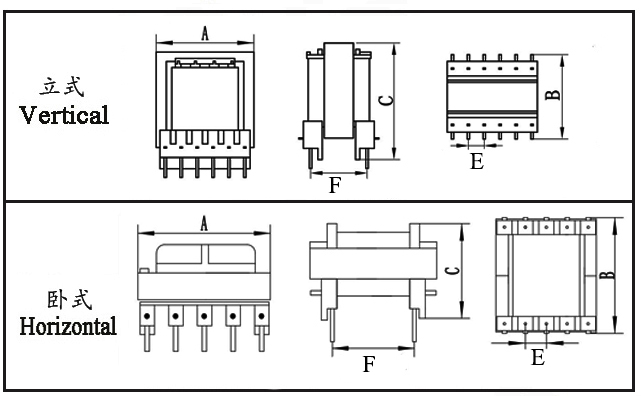
Type | Structure
Tурe | Dimension(mm) | Pin Row (mm) | Row Pitch (mm) | OD Pin
(mm) | note | A | B | C | Pin | E | F | EF16-001 | Horizontal | 16.6 | 17.0 | 11.2 | 4+4 | 3.50 | 14.20 | Φ0.6 |
| EF16-002 | Horizontal | 16.6 | 17.0 | 11.2 | 4+4 | 3.50 | 14.20 | Φ0.6 |
| EF16-003 | Horizontal | 16.6 | 17.0 | 11.7 | 5+5 | 2.50 | 13.00 | Φ0.6 |
| EF16-004 | Vertical | 18.0 | 16.5 | 21.0 | 6+6 | 2.50 | 8.75 | SQ0.6*0.6 |
|
* The above are the commonly used bobbin styles of the company.,Other styles are not included for the time being.,Welcome to consult. Our company can customize high - frequency transformers of various specifications according to customer requirements.
EF16 Transformer Performance Analysis The EF16 is a widely used mid-power high-frequency transformer specification, featuring a larger core cross‑sectional area, superior power density, and enhanced heat dissipation compared to the EF12.6. It typically covers a power range of 3–25 W and is suitable for high‑frequency switching power supplies from 20 kHz to 1 MHz, balancing isolation, efficiency, and cost. The following outlines its key performance characteristics.
I. Basic Electrical Performance
Operating frequency: 20 kHz – 1 MHz (most common: 50 kHz – 500 kHz)
Output power: 3 – 25 W (depending on topology, cooling, and frequency)
Insulation withstand voltage: Typically 1.5 – 3 kV AC / 1 min, meeting UL / VDE / IEC safety standards
Operating temperature range: –40 °C to +125 °C (core Curie temperature ≥210 °C)
Inductance: Customizable via turns ratio; typically tens of µH to a few mH (measured at 10 kHz / 100 kHz)
Leakage inductance: 30 – 80 µH (at 100 kHz; can be reduced with optimized winding structure)
DC resistance (DCR): Primary 0.1 – 5 Ω, secondary in the mΩ range (determined by wire gauge and turns)
II. Core and Magnetic Properties
Core specification: EF16 / E16/8/5 ferrite; common materials include PC40, N87, 3C90, etc.
Saturation flux density (Bs): 380 – 450 mT, resistant to saturation, suitable for wide‑input‑voltage designs
Core losses: Low iron loss at high frequencies, suitable for flyback, forward, LLC and other topologies
Adjustable air gap: Can be gapped as needed to stabilize inductance, avoid saturation, and reduce temperature rise
III. Losses and Efficiency
Copper loss: Optimized wire gauge/stranding minimizes skin effect; low DCR helps control temperature rise
Iron loss: Matched core material and operating point keep high‑frequency losses low
Typical efficiency: 88% – 94% (under full load with appropriate frequency and topology)
IV. Isolation and Safety Performance
Inter‑winding insulation: Insulating tape / bobbin isolation; creepage and clearance meet safety standards
Dielectric strength: 1.5 – 3 kV AC, suitable for isolating high‑voltage from low‑voltage circuits, driver/sensing isolation, etc.
Moisture/heat resistance: Optional epoxy potting enhances reliability and environmental ruggedness
V. Structural and Assembly Features
Moderate size: A‑dimension = 16 mm; offers significantly higher power than EF12.6 while remaining compact
Mounting options: Vertical/horizontal; standardized pinout compatible with through‑hole or SMT assembly
Improved heat dissipation: Larger core volume results in lower thermal resistance, supporting higher power density
EF16 Transformer Overview The EF16 transformer is a high-frequency component positioned between small-size (e.g., EF12.6) and medium-power models. It is widely used in 3–25W isolated power supplies, driver circuits, and signal-sampling applications. The following analysis covers seven dimensions: structure/size, electrical performance, magnetic properties, loss/efficiency, isolation/safety, manufacturing feasibility, and application compatibility.
1. Structure and Size Characteristics
Size Positioning: A-dimension = 16 mm; a compact mid-power specification offering significantly higher power than EF12.6 while saving PCB space compared to larger cores like EFD20 or E25.
Typical Footprint (vertical): Approx. 18.0×14.0×18.0 mm (varies slightly by manufacturer), suitable for board-mounted power supplies where space is limited but power demand is higher.
Standardized Core and Bobbin: • Core: EF16/E16/8/5 ferrite – symmetrical, consistent assembly. • Bobbin: Vertical/horizontal options; standard pin spacing compatible with through‑hole and some SMT processes.
Thermal and Mechanical Robustness: • Larger core cross‑section lowers thermal resistance, reducing temperature rise at the same power level. • Tight core‑bobbin fit, combined with optional potting, improves resistance to shock, vibration, and moisture.
2. Electrical Performance
Power Range and Frequency Suitability: • Typical power: 3–25 W (mainly flyback, also suitable for forward, LLC, push‑pull, etc.). • Operating frequency: 20 kHz – 1 MHz, with mainstream use at 50 kHz – 500 kHz to balance efficiency and EMI.
Controllable Inductance and Leakage Inductance: • Inductance: Tens of µH to a few mH (measured at 10 kHz/100 kHz), precisely adjustable via turns and air‑gap. • Leakage inductance: 30–80 µH (100 kHz) – can be further reduced by layered tight‑winding or interleaving, improving loop stability and EMI control.
DC Resistance (DCR) and Current Capability: • Primary DCR: 0.1–5 Ω (determined by wire gauge and turns). • Secondary DCR: mΩ‑range, suitable for higher‑current outputs (e.g., 5 V/3 A, 12 V/1.5 A). • Wire gauge/strand count can be optimized to reduce copper loss and temperature rise.
3. Core and Magnetic Properties
Common Core Materials: PC40, N87, 3C90, etc. – low high‑frequency loss and good temperature stability.
Saturation Flux Density (Bs): 380–450 mT, suitable for wide input‑voltage ranges (e.g., 85–265 V AC).
Core Loss and Operating Point: • Hysteresis + eddy‑current losses perform excellently in the 50–500 kHz range, ideal for high‑efficiency switching supplies. • Optional air‑gap stabilizes inductance, prevents saturation, and reduces temperature rise and magnetic noise.
Temperature Characteristics: • Core Curie temperature ≥210 °C – maintains magnetization at high temperatures. • Operating temperature: –40 °C to +125 °C, meeting demanding environments (industrial, automotive, outdoor).
4. Loss and Efficiency
Copper Loss (Winding Loss): • Optimized wire gauge/stranding minimizes skin effect and keeps DCR low. • Multi‑strand/Litz‑wire options further reduce high‑frequency copper loss.
Core Loss (Iron Loss): • Matched material and operating point keep high‑frequency core loss low. • Proper flux‑density (Bm) design avoids oversaturation, which would increase temperature rise and reduce efficiency.
Typical Efficiency: • 88%–94% for 5–20 W flyback supplies at full load. • Light‑load efficiency remains good, suitable for applications with strict standby‑power requirements.
5. Isolation and Safety
Insulation Withstand Voltage: • Routine inter‑winding rating: 1.5–3 kV AC/1 min (some versions up to 4 kV AC). • Complies with UL, VDE, IEC, etc. – suitable for HV‑LV isolation, driver isolation, and signal‑sampling isolation.
Creepage and Clearance: • Bobbin structure + insulating tape/sleeving ensures safe distances, preventing breakdown and tracking.
Application Suitability: • Ideal for AC‑DC/DC‑DC isolated supplies, gate‑drive isolation, and current/voltage sensing.
Environmental Reliability: • Optional epoxy potting enhances moisture, dust, and salt‑spray resistance. • Suitable for long‑term operation in industrial control, communications, automotive, etc.
6. Manufacturing and Mass‑Production Features
Mature Winding Process: • Compatible with automatic winding machines; layered tight‑winding, interleaving, and sandwich winding are all feasible. • High consistency supports high‑volume production.
Assembly and Soldering Friendliness: • Standard vertical/horizontal pinout ensures stable through‑hole soldering; some versions support SMT reflow. • Tight core‑bobbin tolerances improve assembly efficiency.
Cost‑Effective: • Standardized cores and bobbins, mature supply chain, moderate cost. • Offers better cost‑performance than non‑standard EFD or E‑series cores of similar power.
7. Application Suitability
Consumer Electronics: • 5–24 W chargers/adapters (phones, tablets, small appliances). • Set‑top boxes, routers, fiber‑modem auxiliary power.
Industrial and Control Systems: • PLC, sensor, transmitter isolated power/drivers. • Instrumentation, measurement‑device analog/digital isolation.
Communications and Networking: • PoE low‑power modules, network‑card/communication‑module isolated power. • Server/switch auxiliary power, driver supplies.
Automotive Electronics (automotive‑grade versions): • On‑board charger (OBC) auxiliary power. • BMS isolated sensing, lighting/infotainment isolated drivers.
Lighting and Home Appliances: • LED driver power supplies (isolated, 5–20 W). • Smart‑lighting/dimming modules, small‑appliance control‑board power.
EF16 Transformer Application Scenarios I. Consumer Electronics
Chargers/Adapters: 5–24W power supplies for mobile phones, tablets, small home appliances, and digital devices.
Networking Equipment: Auxiliary power supplies for routers, fiber modems, set-top boxes, and switches.
Smart Home: Isolated power supplies for smart outlets, gateways, cameras, and electronic locks.
Portable Devices: Isolated DC-DC converters for power banks, handheld devices, and Bluetooth speakers.
II. Industrial Control
PLCs, Industrial Control Boards, Relays, Solenoid Valves: Isolated drive circuits and auxiliary power supplies.
Sensors, Transmitters, and Meters: Signal isolation and auxiliary power supplies for instruments.
Industrial Communication: Isolation for RS485/CAN buses, analog/digital signal isolation sampling.
Motor Control: Isolated gate-drive power supplies for IGBT/MOSFET circuits.
III. Communication and Networking
PoE (Powered Device) low-power isolated power supplies.
Communication Modules, Network Cards, Optical Modules: Isolated power supplies.
Servers/Base Stations: Auxiliary and monitoring power supplies.
IV. Automotive Electronics (Automotive-grade)
On-board Chargers (OBC) and DC-DC Auxiliary Power Supplies.
Battery Management Systems (BMS): Isolated voltage/current sampling.
Automotive Lighting, Infotainment, Instrument Clusters, and Sensors: Isolated power supplies.
V. Lighting and Home Appliances
5–20W Isolated LED Driver Power Supplies.
Smart Lighting, Dimming Modules, Motion-activated Lights: Control power supplies.
Small Appliances: Power supplies for control boards in fans, humidifiers, and coffee makers.
VI. Typical Circuits/Topologies
Flyback AC-DC/DC-DC Isolated Power Supplies.
Forward, Push-Pull, Half-Bridge Drive Isolation.
Signal/Sampling Isolation and Gate-Drive Isolation.
Wide-Input-Voltage (85–265V AC) Low-Power Supplies.
|


