* Product parameters Operating frequency:10kHz-500KHz Operating temperature:-40℃ to +125℃ Storage temperature:-25℃ to +85℃ Storage humidity:30 to 95%
* Product features Small size, space-saving Suitable for high frequency, low loss High power density, can output power even in small size Good insulation, high voltage resistance, safe and reliable Wide temperature range, strong stability Flexible winding, can be customized Mature process, low cost, easy for mass production Convenient installation, suitable for automated production
* Typical application fields Adapter / Charger: 10–45W medium - power supplies (laptops, tablets, small household appliances) Industrial / Industrial control: PLC, sensors, instrument isolation power supplies / drivers Communication / Network: routers, optical modems, PoE medium - power modules Household appliances / LED: LED drivers, small household appliance control board power supplies Automotive electronics (automotive - grade): on - board auxiliary power supplies, BMS isolation sampling / drivers
* Product standards UL, RoHS, 3C, CQC * Dimensions and specifications 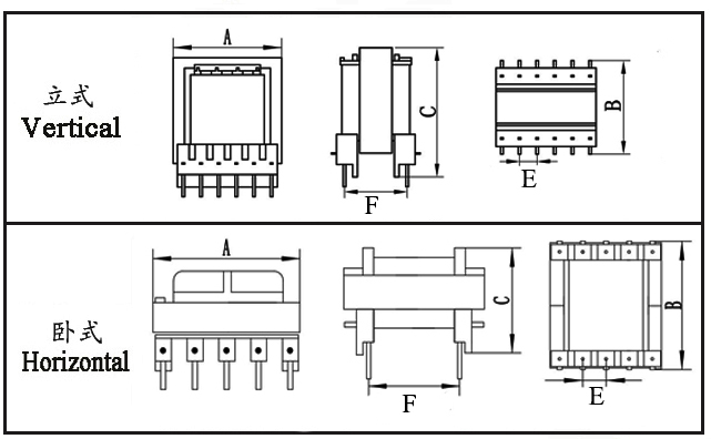
Type | Structure
Tурe | Dimension(mm) | Pin Row (mm) | Row Pitch (mm) | OD Pin
(mm) | note | A | B | C | Pin | E | F | EF20-001 | Horizontal | 20.5 | 20.6 | 15.1 | 4+4 | 5.00 | 15.00 | Φ0.7 |
| EF20-002 | Horizontal | 20.5 | 20.6 | 15.1 | 4+4 | 5.00 | 15.00 | Φ0.7 |
| EF20-003 | Horizontal | 20.5 | 20.6 | 16.6 | 5+5 | 3.80 | 15.40 | Φ0.6 |
| EF20-004 | Vertical | 20.5 | 17.0 | 21.0 | 3+4 | 5.00 | 12.00 | Φ0.7 |
| EF20-005 | Horizontal | 23.6 | 30.0 | 14.5 | 5+5 | 4.00 | 23.60 | SQ0.7*0.7 |
|
* The above are the commonly used bobbin styles of the company,Other styles are not included for the time being,Welcome to consult. Our company can customize various specifications of high - frequency transformers according to customer requirements.
EF20 Transformer Performance Analysis The EF20 is a mainstream mid‑power high‑frequency transformer specification, offering a larger core cross‑sectional area and enhanced thermal performance compared to smaller models. It typically covers a power range of 10–50 W and is suitable for high‑frequency switching power supplies from 20 kHz to 1 MHz, balancing power density, isolation grade, and cost. The following analysis outlines its key performance characteristics.
I. Basic Electrical Performance
Operating Frequency: 20 kHz – 1 MHz (most common: 50 kHz – 500 kHz)
Output Power: 10 – 50 W (depending on topology, cooling, and frequency)
Insulation Withstand Voltage: Typically 1.5 – 3 kV AC / 1 min; versions up to 4 kV AC available
Operating Temperature Range: –40 °C to +125 °C (core Curie temperature ≥210 °C)
Inductance: Customizable via turns ratio; typically tens of µH to a few mH (measured at 10 kHz / 100 kHz)
Leakage Inductance: 20 – 70 µH (at 100 kHz; can be further reduced with optimized winding structure)
DC Resistance (DCR): Primary 0.1 – 3 Ω, secondary in the mΩ range (determined by wire gauge and turns)
II. Core and Magnetic Properties
Core Specification: EF20 / E20/10/6 ferrite; common materials include PC40, N87, 3C90, etc.
Saturation Flux Density (Bs): 380 – 450 mT, suitable for wide‑input‑voltage designs (e.g., 85–265 V AC)
Core Losses: Low iron loss at high frequencies, suitable for flyback, forward, LLC, push‑pull, and other topologies
Adjustable Air Gap: Can be gapped as needed to stabilize inductance, avoid saturation, and reduce temperature rise
III. Losses and Efficiency
Copper Loss: Optimized wire gauge/stranding minimizes skin effect; low DCR helps control temperature rise
Iron Loss: Matched core material and operating point keep high‑frequency losses low
Typical Efficiency: 90% – 95% (under full load with appropriate frequency and topology)
IV. Isolation and Safety Performance
Inter‑winding Insulation: Insulating tape / bobbin isolation; creepage and clearance distances comply with UL, VDE, IEC standards
Dielectric Strength: 1.5 – 3 kV AC (suitable for HV‑LV isolation, driver isolation, and signal‑sampling isolation)
Environmental Reliability: Optional epoxy potting improves resistance to moisture, dust, and salt‑spray
V. Structural and Assembly Features
Moderate Size: A‑dimension = 20 mm; provides significantly higher power than EF16 while remaining compact
Mounting Options: Vertical/horizontal; standardized pinout compatible with through‑hole or SMT assembly
Improved Heat Dissipation: Larger core volume results in lower thermal resistance, supporting higher power density
EF20 Transformer Detailed Analysis The EF20 is a principal mid‑power high‑frequency transformer model. Compared to the EF12.6 and EF16, it offers significantly improved power handling, thermal performance, current density, and structural strength, while maintaining favorable space efficiency and cost advantages. Below is a detailed explanation across seven dimensions: structure/size, electrical performance, magnetic properties, losses/efficiency, isolation/safety, manufacturing feasibility, and application compatibility.
I. Structure and Size CharacteristicsSize Positioning
A‑dimension = 20 mm – a compact mid‑power design that offers a clear power upgrade over the EF16 while using less PCB area than larger cores such as EFD25 or E28.
Typical footprint (vertical): ~22.0×16.0×20.0 mm (varies slightly by manufacturer), suitable for board‑mounted power supplies where space is limited but power demands are higher.
Standardized Core and Bobbin
Core: EF20/E20/10/6 ferrite – symmetrical construction ensures consistent assembly.
Bobbin: Vertical/horizontal options; standardized pin spacing compatible with through‑hole and certain SMT processes.
Thermal and Mechanical Robustness
Larger core cross‑section results in lower thermal resistance, reducing temperature rise at equivalent power levels.
Tight core‑bobbin fit, combined with optional potting, improves resistance to shock, vibration, and moisture.
II. Electrical PerformancePower Range and Frequency Suitability
Typical power: 10–50 W (mainly flyback, also suitable for forward, LLC, push‑pull, etc.).
Operating frequency: 20 kHz – 1 MHz (most common: 50 kHz – 500 kHz), balancing efficiency and EMI.
Controllable Inductance and Leakage Inductance
Inductance: Tens of µH to several mH (measured at 10 kHz/100 kHz), precisely adjustable via turns and air‑gap.
Leakage inductance: 20–70 µH (100 kHz) – can be further reduced by layered tight‑winding or interleaving, improving loop stability and EMI control.
DC Resistance (DCR) and Current Capability
Primary DCR: 0.1–3 Ω (determined by wire gauge and turns).
Secondary DCR: mΩ‑range, suitable for higher‑current outputs (e.g., 5 V/5 A, 12 V/3 A).
Wire gauge/strand count can be optimized to reduce copper loss and temperature rise.
III. Core and Magnetic PropertiesCommon Core Materials
PC40, N87, 3C90, etc. – low high‑frequency loss, good temperature stability.
Saturation flux density (Bs): 380–450 mT, suitable for wide input‑voltage ranges (e.g., 85–265 V AC).
Core Loss and Operating Point
Hysteresis + eddy‑current losses perform excellently in the 50–500 kHz range, ideal for high‑efficiency switching supplies.
Optional air‑gap stabilizes inductance, prevents saturation, and reduces temperature rise and magnetic noise.
Temperature Characteristics
Core Curie temperature ≥210 °C – maintains magnetization at high temperatures.
Operating temperature: –40 °C to +125 °C, meeting demanding industrial, automotive, and outdoor environments.
IV. Loss and Efficiency CharacteristicsCopper Loss (Winding Loss) Core Loss (Iron Loss)
Matched material and operating point keep high‑frequency core loss low.
Proper flux‑density (Bm) design avoids oversaturation, which would increase temperature rise and reduce efficiency.
Typical Efficiency
90%–95% for 10–40 W flyback supplies at full load.
Light‑load efficiency remains good, suitable for applications with strict standby‑power requirements.
V. Isolation and Safety CharacteristicsInsulation Withstand Voltage
Routine inter‑winding rating: 1.5–3 kV AC/1 min (some versions up to 4 kV AC).
Complies with UL, VDE, IEC, etc. – suitable for HV‑LV isolation, driver isolation, and signal‑sampling isolation.
Creepage and Clearance
Bobbin structure + insulating tape/sleeving ensures safe distances, preventing high‑voltage breakdown and tracking.
Suitable for AC‑DC/DC‑DC isolated supplies, gate‑drive isolation, and current/voltage sensing.
Environmental Reliability
Optional epoxy potting enhances moisture, dust, and salt‑spray resistance.
Suitable for long‑term operation in industrial control, communications, automotive, and similar harsh environments.
VI. Manufacturing and Mass‑Production FeaturesMature Winding Process
Compatible with automatic winding machines; layered tight‑winding, interleaving, and sandwich winding are all feasible.
High consistency supports high‑volume production.
Assembly and Soldering Friendliness Cost‑Effective
Standardized cores and bobbins, mature supply chain, moderate cost.
Offers better cost‑performance than non‑standard EFD or E‑series cores of similar power.
VII. Application SuitabilityConsumer Electronics
10–45 W chargers/adapters (laptops, tablets, small appliances).
Auxiliary power for set‑top boxes, routers, fiber modems.
Industrial and Control Systems
Isolated power/drivers for PLCs, sensors, transmitters.
Analog/digital isolation for instruments and measurement devices.
Communications and Networking
PoE mid‑power modules, isolated power for network cards/communication modules.
Server/switch auxiliary and driver power supplies.
Automotive Electronics (Automotive‑grade)
On‑board charger (OBC) auxiliary power.
BMS isolated sensing, lighting/infotainment isolated drivers.
Lighting and Home Appliances
LED driver power supplies (isolated, 10–40 W).
Smart‑lighting/dimming modules, control‑board power for small appliances.
EF20 Transformer Application Scenarios Leveraging its integrated strengths of 10–50W power handling, high-frequency low‑loss operation, strong isolation, excellent thermal performance, and compact structure, the EF20 transformer is widely used in a variety of mid‑power applications requiring electrical isolation for power supplies, drive circuits, and signal‑sampling systems. The detailed application fields are as follows:
I. Consumer Electronics
Chargers/Adapters: 10–45 W power supplies for laptops, tablets, gaming consoles, and small appliances.
Networking Equipment: Auxiliary power supplies for routers, fiber modems, set‑top boxes, switches, and NAS devices.
Smart Home: Isolated power supplies for smart gateways, cameras, central controllers, electronic locks, and sensors.
Portable Devices: Isolated DC‑DC converters for power banks, portable power stations, and handheld instruments.
II. Industrial Control
PLCs, Industrial Control Boards, Relays, Solenoid Valves: Isolated drive circuits and auxiliary power supplies.
Sensors, Transmitters, Instruments: Signal isolation and auxiliary power supplies for measurement devices.
Industrial Communication: Isolation for RS485/CAN/Ethernet buses, analog/digital signal isolation sampling.
Motor Control: Isolated gate‑drive power supplies for IGBT/MOSFET circuits, auxiliary power for servo drives.
III. Communication and Networking
PoE (Powered Device) mid‑power modules (15–30 W): Isolated power supplies.
Communication Modules, Network Cards, Optical Modules, Base Stations: Low‑power auxiliary supplies.
Servers/Switches: Monitoring, management, and driver‑stage isolated power supplies.
IV. Automotive Electronics (Automotive‑grade)
On‑board Chargers (OBC) and DC‑DC Auxiliary Power Supplies.
Battery Management Systems (BMS): Isolated voltage/current sampling and cell‑balancing power.
Automotive Lighting, Infotainment, Instrument Clusters, Sensors, Cameras: Isolated power supplies.
V. Lighting and Home Appliances
10–40 W Isolated LED Driver Power Supplies (indoor lighting, panel lights, downlights).
Smart Lighting, Dimming Modules, Motion‑activated Lights: Control power supplies.
Small Appliances: Power supplies for control boards in fans, humidifiers, coffee makers, and air purifiers.
VI. Medical and Security (Enhanced Safety‑grade Versions)
Medical Equipment: Low‑power isolated auxiliary supplies (meeting requirements such as 2 MOPP).
Security Systems: Isolated power supplies for surveillance cameras, NVRs, access control, and alarm devices.
VII. Typical Circuits/Topologies
Flyback AC‑DC/DC‑DC Isolated Power Supplies (most common application).
Forward, Push‑Pull, Half‑Bridge, LLC mid‑power isolated converters.
Signal/Sampling Isolation, Gate‑Drive Isolation, Auxiliary Power Supplies.
Wide‑Input‑Voltage (85–265 V AC) Mid‑Power Supplies.
|


