* Product Parameters
Operating frequency:10kHz-500KHz Operating temperature:-40℃ to +125℃ Storage temperature:-25℃ to +85℃ Storage humidity:30 to 95%
* Features
The ER11.5 is the most balanced and practical round center-pillar transformer in the 3-5W range. With sufficient power, low leakage inductance, high withstand voltage, multi-channel output capability, and stable mass production, it is the "mainstay general-purpose model" among low-power isolated power supplies.
* Typical application areas
The ER11.5 (A=11.5mm) is the main model of 3W to 5W isolated power supply, covering almost all low-power isolated power supply scenarios such as industrial control, communication, home appliances, lighting, automotive, and IoT. It has extremely strong versatility and the most stable mass production. * Product Standards UL, RoHS, 3C,CQC * Size Specifications 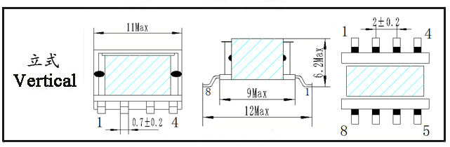
Type | Structure
Tурe | Dimension(mm) | Pin Row (mm) | Row Pitch(mm) | OD Pin
(mm) | note | A | B | C | Pin | E | F | ER11.5-001 | Vertical | 12.0 | 12.2 | 6.0 | 3+3 | 4.00 | 12.20 | SQ0.25*0.7 | SMD | ER11.5-002 | Vertical | 12.0 | 12.2 | 6.0 | 3+3 | 4.00 | 12.20 | SQ0.25*0.7 | SMD | ER11.5-003 | Vertical | 12.0 | 12.2 | 6.0 | 5+5 | 2.00 | 12.20 | SQ0.25*0.7 | SMD | ER11.5-004 | Vertical | 12.0 | 12.2 | 6.0 | 5+5 | 2.00 | 12.20 | SQ0.25*0.7 | SMD |
*The above are commonly used skeleton styles for the company.,Other styles are not included.,Inquiries are welcome. Our company can customize high-frequency transformers of various specifications according to customer requirements.
ER11.5 Transformer is an ultra‑compact, low‑profile surface‑mount high‑frequency transformer. As one of the smaller members of the ER‑core series, it is specifically designed for modern electronics where board space is extremely limited and height is strictly constrained.
I. Core Structure and Physical Characteristics
Core Material: Typically high‑frequency power ferrites such as PC40, PC44, or PC95. These materials offer low loss and high permeability at frequencies ranging from tens of kHz to several MHz, making them well‑suited for switching‑power‑supply applications.
Form Factor:
Low Profile: The ER‑type core has a cylindrical center post but an overall flat profile, effectively minimizing transformer height.
Center and Side Posts: Features one center post and two side posts. Windings are normally wound on the center post. This structure helps reduce leakage inductance and provides a good thermal path (heat can be conducted from the center post to the entire core surface).
Surface‑Mount (SMD): The ER11.5 is usually designed as a surface‑mount component with pins on the bottom, enabling automated pick‑and‑place assembly.
II. Key Electrical Parameters and Characteristics
Power Range: Very low power. Due to its extremely small size, the typical output power ranges from about 0.5 W to 3 W, depending on operating frequency, topology, and cooling conditions. Mainly used for signal isolation, auxiliary power supplies, and other low‑power applications.
Operating Frequency: High frequency. Designed for operation typically between 100 kHz and 1 MHz (or higher). High frequency is key to achieving its miniature size, because higher frequencies allow smaller core volumes and fewer winding turns to transfer the same power.
Inductance and Turns:
Its Aₗ value (inductance factor) is very small, meaning each turn produces very little inductance.
Consequently, relatively more primary turns are needed to obtain the required main inductance (e.g., for energy storage in flyback topologies). This demands finer wire gauges and precise winding techniques.
Isolation Characteristics:
As a transformer, it provides galvanic isolation between primary and secondary. The isolation voltage, depending on insulation design and process, typically ranges from several hundred volts to several kilovolts (e.g., 1.5 kV AC).
This is its core value in applications such as power modules, communication interfaces, and isolated sampling circuits.
Advantages and Disadvantages:
III. Typical Applications
Portable / Wearable Devices – Smart watches, wireless earbuds, health monitors. – Reason:ultra‑low profile saves thickness.
Ultra‑Thin Adapters & Chargers – USB‑C PD adapters, slim‑line power modules. – Reason:meets height constraints while providing isolation.
High‑Density Board‑Level Power – Isolated DC‑DC modules on communication boards, industrial I/O modules. – Reason:small footprint allows placement near ICs.
Signal Isolation & Interface Circuits – Isolated RS‑485, CAN, SPI, I²C interfaces. – Reason:provides galvanic isolation with minimal space.
Auxiliary / Bias Supplies in Compact Systems – Power for gate‑drive circuits, isolated feedback paths, sensor supplies. – Reason:delivers low power with full isolation in tight spaces.
IV. Design Considerations
Thermal Management: Ensure adequate PCB copper area for heat spreading, and consider forced airflow if power approaches the upper limit.
Winding Strategy: Use fine‑gauge wire (e.g., AWG 38‑44) and possibly triple‑insulated wire if safety‑grade isolation is required. Layer‑winding or bank‑winding techniques can help manage leakage inductance.
Driver Selection: Pair with a high‑frequency controller (e.g., operating at 200 kHz–500 kHz) to minimize the required inductance and turns.
Supplier Qualification: Choose manufacturers with proven capability in micro‑transformer production and strict process control to ensure lot‑to‑lot consistency.
ER11.5 Transformer Characteristics
1. Structure and Size Features
ER-type circular center post structure – ensures uniform winding and high consistency.
Size A = 12 mm – volume sits between ER9.5 and ER14.5.
Common bobbin pinouts: 3+3, 5+5 pins – SMD (surface‑mount) compatible.
Larger winding window – easily accommodates multiple outputs (dual, triple, etc.).
2. Power and Load Capability
Rated power: 3 W – 4 W, maximum up to 5 W.
Significantly higher load capacity compared to ER7.5 and ER9.5.
Ideal for auxiliary power, control power, and low‑power main power supplies.
3. Electrical Performance
Low leakage inductance: typically ≤ 4.5 μH – results in good EMI performance and lower voltage spikes.
High‑frequency compatibility: 20 kHz – 300 kHz, low core loss at high frequencies.
High isolation withstand voltage: standard 2 kV AC, can be designed for 3 kV AC.
Insulation class: Class B (130 °C) / Class F (155 °C) – meets major safety standards (UL, IEC, EN).
Low temperature rise, high efficiency, stable and reliable under continuous full load.
4. Manufacturing and Mass‑Production Features
Circular center post – easy to wind, low risk of wire breakage, high production yield.
Excellent coil coupling – ensures consistent inductance parameters.
Well‑suited for automated production – stable cost for high‑volume orders.
5. Key Advantages over ER7.5 / ER9.5
Higher power range – 3 W to 5 W class.
Larger winding window – better suited for multi‑output designs.
Improved thermal performance – lower temperature rise, higher reliability.
Exceptional versatility – widely used in industrial control, communications, home appliances, and automotive electronics.
ER11.5 Transformer Application Scenarios
I. Positioning
Power Range: 3 W – 5 W
Structure: ER-type circular center post – low leakage inductance, high isolation
Size A: 12 mm
Ideal for: Auxiliary power supplies, isolated control power, multi‑output low‑power systems
II. Key Application Fields1. Consumer Electronics & Power Adapters
Primary/auxiliary power for chargers and adapters
Internal power supplies for set‑top boxes, routers, optical modems, and gateways
Small switching power supplies, USB sockets, fast‑charging protocol power supplies
Features: Moderate size, low leakage inductance, easy EMI compliance
2. Industrial Control & Industrial Power Systems
Control power for PLCs, I/O modules, and driver boards
Auxiliary start‑up power for inverters, servo drives, and welding machines
Isolated power for sensors, transmitters, and instruments
Multi‑output industrial modules (±5 V, ±12 V, 5 V + 12 V, etc.)
Features: Wide temperature range, high isolation, long‑term stability, strong noise immunity
3. Lighting & LED Drivers
Low‑power LED constant‑current drivers
Auxiliary power for downlights, panel lights, and industrial lamps
Power for intelligent lighting control modules
Features: Low temperature rise, high reliability, suitable for continuous operation
4. Communication & Networking Equipment
Optical modules, 5G small‑cell base stations, DTUs, and data‑transmission modules
Isolated drive power inside PoE (Power over Ethernet) modules
Isolated power for Ethernet ports and communication interfaces
Features: Low noise, low leakage inductance, minimal signal interference
5. Smart Home & IoT
Smart switches, sockets, and security cameras
Curtain motors, smart locks, and access control systems
Isolated power for wireless modules (Wi‑Fi/Bluetooth/LoRa)
Features: Supports both SMD and through‑hole mounting, flexible PCB layout
6. Automotive Electronics (Automotive‑grade versions available)
Automotive sensors and lighting control
Low‑power isolated supplies for body control modules (BCM)
Temperature Range: -40 °C to +125 °C
III. Core Advantages of ER11.5 in Applications
Most versatile model in the 3 W–5 W range
Capable of multi‑output designs (dual/triple outputs)
Low leakage inductance simplifies EMI design and certification
High isolation voltage (2 kV / 3 kV) meets stringent safety standards
Optimal balance among size, power, and cost
|


