* Product Parameters
Operating frequency:10kHz-500KHz Operating temperature:-40℃ to +125℃ Storage temperature:-25℃ to +85℃ Storage humidity:30 to 95%
* Features
The ER14.5 is a versatile surface-mount high-frequency transformer that strikes the best balance between power, size, cost, safety, and supply chain. When your design requires a compact, reliable, inexpensive isolated power supply solution with a power rating of 10W or less, the ER14.5 is almost always the safest and most conventional first choice.
* Typical application areas Power adapters and chargers (AC-DC) Onboard isolated power supply module(DC-DC) LEDLighting driver Consumer electronics and portable devices Renewable Energy and Power Systems
* Product Standards UL, RoHS, 3C,CQC
* Size Specifications 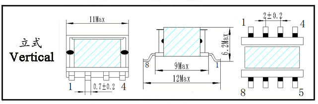
Type | Structure
Tурe | Dimension(mm) | Pin Row (mm) | Row Pitch(mm) | OD Pin
(mm) | note | A | B | C | Pin | E | F | ER14.5-001 | Vertical | 15.0 | 16.0 | 7.0 | 5+5 | 2.50 | 16.00 | SQ0.3*0.7 | SMD |
*The above are commonly used skeleton styles for the company.,Other styles are not included.,Inquiries are welcome. Our company can customize high-frequency transformers of various specifications according to customer requirements.
ER14.5 Transformer is a compact, surface-mount high-frequency transformer that achieves an excellent balance among power density, manufacturability, and cost.
I. Core Structure and Physical Characteristics
Core Material: Primarily high-frequency, low-loss power ferrites such as TDK PC40 (equivalent to Ferroxcube 3C90), or higher-performance grades like PC44 (3C94) and PC47 (3C95). These materials offer superior performance within the 100 kHz to 500 kHz range.
Form Factor:
Standard Low‑Profile Design: Maintains the classic ER‑series flat cylindrical center‑post structure, effectively controlling overall height.
Good Mechanical Stability: The 14.5 mm span provides ample footprint for robust soldering and reliable mounting on PCBs.
Excellent SMD Compatibility: A leading model for surface‑mount transformers, with mature pin layout and high‑yield automated assembly.
II. Key Electrical Parameters and Features
Power Range: Medium‑low power core.
Typical continuous output power: 3 W to 10 W (under typical flyback topology at 100‑200 kHz).
Peak/intermittent power can reach 12 W to 15 W, often used in auxiliary or control power supplies for fast chargers.
This power range covers a vast number of consumer and industrial applications.
Operating Frequency: Mainstream high‑frequency band. Optimal efficiency range: 65 kHz to 300 kHz, fully compatible with mainstream QR (quasi‑resonant) and CCM/DCM flyback controllers.
Inductance and Window Utilization:
Compared to ER11.5, the higher Aₗ value means fewer turns are needed to achieve the same inductance, allowing the use of thicker wire and reducing copper loss.
Larger window area provides significant design flexibility: ✓ Supports more windings (e.g., multiple outputs). ✓ Enables “sandwich winding” for better coupling and lower leakage inductance. ✓ Accommodates sufficient insulation tape and barriers to meet reinforced insulation (e.g., 4000 VAC) or basic insulation requirements with ample safety margin.
Isolation and Safety:
Ample window space allows strict compliance with safety standards (UL, CE, etc.), making it a star model that balances small size with high safety certification.
Common isolation voltages: 3000 VAC or 4000 VAC (depending on insulation design), meeting most consumer and industrial equipment requirements.
Advantages and Limitations:
Advantages: ✓ Optimal balance of performance and size – offers substantial power and excellent design flexibility in a compact form. ✓ High cost‑effectiveness – mature supply chain and high volume result in competitive unit cost. ✓ Improved thermal performance – larger core volume provides greater thermal mass and surface area, making temperature rise easier to control than ER11.5. ✓ Wide supplier availability – nearly all magnetic component manufacturers offer mature ER14.5 product lines, simplifying selection and sourcing.
Limitations: ✓ Clear power ceiling – continuous output above 10 W is challenging; larger models (e.g., ER20, ER25) should be considered. ✓ Not the lowest profile – for ultra‑thin designs (e.g., main transformer in GaN‑based ultra‑slim chargers), planar transformers or flatter cores (e.g., PQ types) may be preferred.
III. Typical Applications
Consumer Power Adapters / Fast Chargers – auxiliary power, control power, or main power in compact designs.
Industrial Control & Automation – PLCs, servo drives, I/O module power supplies.
LED Lighting Drivers – constant‑current drivers for downlights, panel lights, etc.
Network/Communication Equipment – PoE modules, optical transceivers, 5G small‑cell power.
Home Appliances & IoT – smart home devices, gateways, sensor nodes.
IV. Why Choose ER14.5?
Power‑size sweet spot – ideal for 3 W–10 W applications where space is constrained but performance cannot be compromised.
Design‑friendly – large window allows multi‑output, improved insulation, and lower leakage inductance.
Proven and cost‑effective – mature technology, reliable supply, and competitive pricing.
ER14.5 Transformer, as a classic industrial standard component, features distinct characteristics that can be summarized in the following key aspects:
1. The “Golden Balance Point” of Performance and SizeThis is the most fundamental characteristic of the ER14.5. It achieves an optimal trade‑off between “small enough” and “capable enough”:
Compact Size: With an outer width of 14.5 mm and a low‑profile structure, it can be easily integrated into high‑density PCBs, meeting the miniaturization demands of modern electronics.
Adequate Power: Its typical power range of 3 W to 10 W precisely covers a vast number of medium‑low‑power applications—from auxiliary power in chargers to onboard isolated DC‑DC modules—making it exceptionally versatile.
2. Design Flexibility and High Safety‑Standard CompatibilityThanks to its relatively generous window area, the ER14.5 offers significant advantages over smaller models (e.g., ER11.5):
Flexible Winding: Can accommodate multiple output windings and supports “sandwich winding” to optimize coupling and reduce leakage inductance.
Reliable Insulation: Allows sufficient insulation layers (e.g., Mylar tape, barriers) to be added easily, meeting reinforced insulation requirements of 3000–4000 VAC with margin. It is the preferred choice for designs that demand both small size and high safety certification.
3. Excellent High‑Frequency Performance and Efficiency
Utilizes high‑frequency, low‑loss ferrite cores such as PC40/PC44/PC47, delivering high efficiency and low core loss at mainstream switching frequencies (65 kHz to 300 kHz).
Perfectly matches popular power‑management ICs like QR flyback and PWM controllers.
4. Exceptional Cost‑Effectiveness and Mature Supply Chain
Optimal Cost: High production volumes result in highly competitive unit costs, making it the preferred choice for cost‑sensitive designs.
Mature Ecosystem: Nearly all power‑IC manufacturers provide reference designs based on the ER14.5, and magnetic‑component suppliers offer a vast array of ready‑made solutions and stock. This simplifies selection, ensures stable supply, and reduces development risks.
5. Surface‑Mount Process and Reliability
Standard SMD (surface‑mount) package enables fully automated production, ensuring consistent quality and robust soldering.
Significantly reduces labor costs and assembly defect rates.
ER14.5 Transformer: Typical Application Fields
I. Power Adapters & Chargers (AC‑DC)This is the most extensive application area for the ER14.5, especially with the proliferation of fast‑charging technology.
Phone / Smart‑Device Fast‑Chargers:
As an auxiliary (standby) power supply: Provides isolated, low‑power voltage (e.g., 12 V or 5 V) for internal PWM controllers and protocol ICs. This is one of its most classic applications.
As the main power transformer (medium‑low power): Used directly as the flyback transformer in 5 W–12 W chargers.
Home Appliance / Smart‑Home Power Supplies:
Auxiliary or main power for TVs, audio systems, set‑top boxes, and smart speakers.
Built‑in AC‑DC power modules for routers and optical modems.
Control‑board power for small appliances (e.g., coffee makers, air purifiers).
II. On‑Board Isolated Power Modules (DC‑DC)In systems requiring galvanic isolation, the ER14.5 is the core component for building compact isolated DC‑DC modules.
Industrial Control & Automation:
Isolated interface power: Supplies isolated power to the secondary side of industrial‑bus isolated transceivers (RS‑485, CAN, Profibus, etc.) to ensure stable, noise‑immune signal transmission.
Isolated drive power: Provides independent isolated power for IGBT/MOSFET gate drivers, isolated amplifiers, and ADCs.
PLC modules and sensors: Power isolation between different functional blocks inside the module.
Communication & Networking Equipment:
Medical & Test Instruments:
Patient‑monitoring and portable medical devices: Isolates the power between signal‑acquisition circuits and the main control unit to ensure safety.
Isolated‑channel power for oscilloscopes and data‑acquisition cards.
III. LED Lighting Drivers
Smart LED drivers: Serves as the core isolated flyback converter in low‑power LED fixtures (e.g., cabinet lights, decorative strips) that require dimming or color tuning.
Low‑voltage safety lighting: Converts mains voltage to a safe, isolated low voltage (e.g., 12 V/24 V) for LED power.
IV. Consumer Electronics & Portable Devices
Wearables / IoT end‑nodes: Steps down higher voltages (e.g., from a battery pack) to low voltages and supplies isolated circuits.
Drones / RC models: Provides clean, isolated power for flight controllers, video‑transmission systems, and other sensitive circuits, separate from the motor power supply.
Digital products: Internal power conversion in cameras, portable printers, etc.
V. Renewable Energy & Power Systems
PV micro‑inverters / optimizers: Supplies isolated power for detection, communication, and control circuits.
Charging stations / battery management: Used for isolated sampling and communication‑interface power in BMS or charging modules.
Why Choose ER14.5?The ER14.5 becomes almost a reflex‑choice when your design has the following requirements:
Power requirement: Approximately 3 W to 10 W.
Space constraints: Limited PCB area, necessitating surface‑mount (SMD) components to save space and enable automated assembly.
Isolation need: Must meet basic or reinforced insulation (e.g., 1500 VAC–4000 VAC) without excessive volume.
Cost sensitivity: Requires the best balance among performance, reliability, and cost.
Development risk: Prefers a mature solution with abundant reference designs and supply‑chain support to speed development and ensure stability.
|


