* Product Parameters
Operating frequency: 10kHz-500KHz Operating temperature: -40℃ to +125℃ Storage temperature: -25℃ to +85℃ Storage humidity: 30 to 95%
* Features The EE10 transformer, thanks to itsMiniature size, excellent high-frequency performance and high cost-effectivenessIt plays a crucial role in modern compact electronic devices. It plays a crucial role. Its typical application areas are mainly concentrated in...Low-power, high-density, high-frequency power conversion and signal processingScene.
* Typical application areas Low-power offline switching power supplyAC-DC) DC-DCPower modules (isolated and non-isolated) High-frequency, ultra-thin adapters and chargers Isolated gate driver Signal and pulse transformers Power inductor (used as an energy storage inductor)
* Product Standards UL, RoHS, 3C,CQC
* Size Specifications 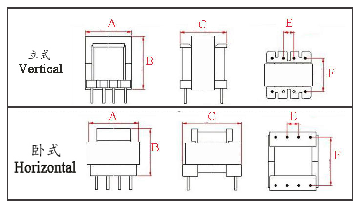
Type | Structure
Tурe | Dimension mm | Pin Row mm | Row Pitch(mm) | OD Pin (mm) | note | A | B | C | Pin | E | F | EE10-001 | Vertical | 10.5 | 10.0 | 11.0 | 4+4 | 2.5 | 8.0 | Φ0.50 |
| EE10-002 | Horizontal | 11.0 | 12.5 | 11.0 | 4+4 | 2.5 | 10.5 | Φ0.60 |
| EE10-003 | Horizontal | 11.0 | 11.5 | 11.0 | 2+2 | 5.0 | 9.0 | Φ0.60 | Double slots | EE10-004 | Horizontal | 11.0 | 11.5 | 11.0 | 2+2 | 5.0 | 9.0 | Φ0.60 | Single slot | EE10-005 | Horizontal | 11.0 | 12.5 | 13.5 | 4+4 | 2.5 | 10.4 | Φ0.60 |
|
*The above are commonly used skeleton styles for the company.,Other styles are not included.,Inquiries are welcome. Our company can customize high-frequency transformers of various specifications according to customer requirements.
Electrical Parameters of the EE10 Transformer The EE10 is one of the most classic low-power cores in high-frequency switching power supplies. It is a standardized small E-type core, named for its side leg length of 10mm. It is specifically designed for compact, high-frequency isolated switching power supplies under 10W (typically 3-7W) and is widely used in consumer electronics adapters, auxiliary power supplies, and other applications. I. Physical and Structural Parameters 1. Standard Model and Dimensions
Complete Model: EE10.2/11.2/4.8 (Slight variations may exist between manufacturers, e.g., EE10/11/5)
Dimension Interpretation:
A: 10.2 mm
B: 11.2 mm
C: 4.8 mm
Physical Structure: It consists of two "E"-shaped ferrite cores paired together to form a closed magnetic circuit (requires an air gap). 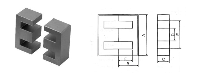
2. Standard Bobbin Specifications The corresponding bobbin typically features 4+4 pins (four for the primary side and four for the secondary side, used for layer jumping and meeting safety standards). Both vertical and horizontal mounting options are available.
II. Detailed Explanation of Core Electrical Parameters The following parameters are the essential foundation for transformer design calculations, derived from typical data of mainstream ferrite materials (such as TDK PC40, Ferroxcube 3C90, etc.). Parameter Name | Symbol | Typical Value Range | Unit | Physical Meaning & Design Application | Effective Core Cross-Sectional Area | Ae | 10.0 - 12.5 | mm² | 【Most Critical Parameter】 Equivalent area through which magnetic flux passes. Used to calculate turns: N = V * t / (Ae * ΔB). Directly determines voltage per turn. | Effective Magnetic Path Length | Le | 25.0 - 27.0 | mm | Average closed path length of magnetic flux. Used to calculate core reluctance,core loss, and magnetic field strength (H). | Core Volume | Ve | Approx. 261 - 320 | mm³ | Ae * Le. Related to total energy storage capacity and temperature rise capability of the core. | Inductance Factor (Ungapped) | AL | 800-950 | nH/N² | Inductance generated per square turn (without air gap). | Curie Temperature | Tc | > 200 | °C | Temperature at which the ferrite material loses its magnetic properties. Operating temperature must be well below this value. |
III. Power Capability and Design Boundaries
Continuous Output Power:
Flyback Topology: 3W - 7W @ 60-100kHz. This is its most typical application range.
Forward Topology: Theoretically can reach 10W+, but implementation is difficult within the small EE10 window area due to the need for a reset winding, making it less commonly used.
Power Limiting Factors:
Temperature Rise: Small volume and limited heat dissipation area mean heat generated from core and copper losses can easily cause excessive temperature rise (typically required <60K).
Window Utilization Factor: Small Aw makes winding difficult when multiple insulation layers or multiple outputs are required.
Saturation Limit: Careful design is needed to prevent saturation under wide input voltage ranges and large transient loads.
IV. Typical Application Scenarios
Mobile Phone/IoT Device Chargers: Standard outputs like 5V/1A, 5V/1.5A.
Standby Power Supplies for Household Appliances: Auxiliary +5V or +3.3V power for MCUs inside TVs, air conditioners, washing machines, etc.
DC-DC Isolation Modules: Isolated power for industrial communication interfaces (e.g., RS-485).
PoE (Power over Ethernet) Powered Devices: Network cameras, wireless access points, etc.
LED Driver Power Supplies: Low-power bulb lamps, LED strip drivers.
V. Key Points in Transformer Design
Air Gap Design is Core
Purpose: Store energy, prevent DC bias saturation, adjust AL value.
Method: Typically ground on the center leg of the core. Air gap length lg = (μ0 * Np² * Ae) / Lp, where Lp is the target primary inductance.
Effect: Air gap increases leakage inductance, requiring optimization through techniques like sandwich winding (secondary wound between two primary layers).
Loss and Temperature Rise Management
Core Loss: Proportional to frequency (f) and a power of flux density swing (ΔB). Low-loss materials (e.g., PC44/PC47) are needed at high frequencies.
Copper Loss: Proportional to the square of RMS current and winding resistance. Proper wire gauge must be selected based on skin depth, or multiple strands can be used in parallel.
Balancing: Increasing turns reduces ΔB (decreasing core loss) but increases coil length (increasing copper loss), requiring iterative optimization.
Safety Standards and Insulation Design
Reinforced Insulation: Must withstand required voltage (e.g., 3000VAC/1min) between primary and secondary.
Implementation Methods:
Use triple-insulated wire for secondary windings.
Or, use two or more layers of tape as a barrier between primary and secondary, ensuring sufficient creepage distance (considered in bobbin structure).
Safety Spacing: Minimum electrical clearance must be met between transformer pins on the PCB.
Parasitic Parameter Control
Leakage Inductance: Causes voltage spikes on switching devices. Must be suppressed through winding techniques and circuit snubbers (e.g., RCD clamp).
Distributed Capacitance: Affects EMI and switching losses. Can be reduced by decreasing winding layers and increasing inter-layer insulation.
VI. Selection and Verification Steps
Confirm Requirements: Input/output voltage, power, frequency, topology, insulation class, efficiency target.
Calculate Ap Value: Use formula Ap ≥ (Pout * 10^4) / (K * f * Bmax * J * Ku) for preliminary estimation to verify if EE10 is suitable.
Detailed Design:
Calculate primary turns (Np) based on Ae and ΔB.
Calculate and determine air gap based on AL value and target primary inductance (Lp).
Select wire gauge based on Aw and current density (J), and verify window fill factor (Ku, typically <0.4).
Prototype Fabrication and Testing:
Test inductance, leakage inductance, turns ratio.
Perform load testing to check temperature rise, efficiency, waveforms (for saturation).
Perform safety standard withstand voltage tests.
EE10 Transformer Core Characteristics The EE10 transformer holds an irreplaceable position in the field of low-power switching power supplies due to its standardized dimensions and excellent overall performance. Its core characteristics can be precisely summarized from the following aspects: I. Core Physical and Electrical Characteristics II. Design and Application Characteristics
The "Air Gap is Mandatory" Design Paradigm
This is the most distinctive feature when using the EE10 in flyback transformers. Its ungapped AL value is high, so a precisely ground air gap is essential to reduce the effective AL value, achieve the target inductance, and prevent saturation. Air gap design is key to its performance (energy storage, temperature rise, leakage inductance).
High Dependency on Winding Techniques
Window Utilization is a Challenge: The small window area (Aw) imposes high demands on winding techniques, especially when reinforced insulation (e.g., using triple-insulated wire) or multiple outputs are required.
Sensitive to Parasitic Parameters: Due to its small size and close proximity between windings, leakage inductance and distributed capacitance are relatively significant. Techniques like sandwich winding are necessary for optimization; otherwise, these parameters directly impact switching device stress, efficiency, and EMI.
Stringent Thermal Management Requirements
Typical Application Scenarios
Mobile Phone/IoT Device Chargers: Standard outputs such as 5V/1A, 5V/1.5A.
Standby Power Supplies for Home Appliances: Auxiliary +5V or +3.3V power for MCUs in TVs, air conditioners, washing machines, etc.
DC-DC Isolation Modules: Isolated power supply for industrial communication interfaces (e.g., RS-485).
PoE Powered Devices: Network cameras, wireless access points, etc.
LED Driver Power Supplies: Low-power LED bulbs, LED strip drivers.
|


