* Product Parameters
Operating frequency: 10kHz-500KHz Operating temperature: -40℃ to +125℃ Storage temperature: -25℃ to +85℃ Storage humidity: 30 to 95%
* Features The EE13 transformer, thanks to its Small size, low cost, and moderate power densityIts characteristics have made it a core component in small and medium power switching power supplies for consumer electronics and industrial control. Its application design revolves around its core electrical parameters, aiming to achieve efficient, reliable, and compact energy conversion.
* Typical application areas Auxiliary power supply (standby power supply) transformer:Provides low-power outputs such as +5VSB in large switching power supplies. Charger/Adapter:EE13 or EE16 are commonly used for small and medium power USB chargers and router adapters such as 5V2A and 12V1.5A. The main transformer or inductor in a DC-DC converter module. Drive transformer:In half-bridge, full-bridge and other topologies, it is used to isolate and drive MOSFETs/IGBTs. Common-mode inductor / differential-mode inductor:Its high permeability (no air gap) is used to fabricate inductor components in EMI filters.
* Product Standards UL, RoHS, 3C,CQC * Size Specifications 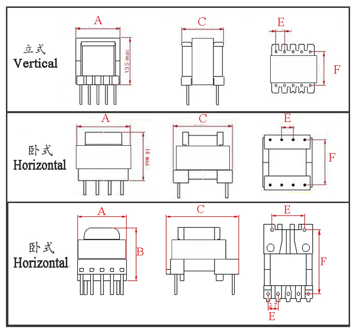
Type | Structure
Tурe | Dimension(mm) | Pin Row (mm) | Row Pitch(mm) | OD Pin(mm) | note | A | B | C | Pin | E | F | EE13-001 | Vertical | 10.5 | 12.5 | 13.0 | 3+3 | 3.0 | 9.0 | Φ0.60 |
| EE13-002 | Vertical | 13.0 | 12.5 | 13.5 | 5+5 | 2.5 | 8.5 | SQ0.50*0.50 |
| EE13-003 | Vertical | 15.5 | 16.5 | 14.5 | 5+2 | 2.5 | 13.0 | Φ0.60 | one side widened | EE13-004 | Horizontal | 14.0 | 14.0 | 13.5 | 5+5 | 2.5 | 10.3 | Φ0.60 |
| EE13-005 | Horizontal | 14.0 | 17.8 | 13.5 | 5+4 | 2.50/3.00 | 15.5 | Φ0.60 | one side widened | EE13-006 | Horizontal | 14.0 | 19.9 | 13.8 | 5+2 | 2.70/9.00 | 16.0 | Φ0.60 | one side widened |
*The above are commonly used skeleton styles for companies.,Other styles are not included.,Inquiries are welcome. Our company can customize high-frequency transformers of various specifications according to customer requirements.
EE13 Transformer The "EE" here refers to the core structure formed by pairing two E-shaped cores, and the "13" indicates a side leg width of 13mm. A complete EE13 core also includes key parameters such as the center leg cross-sectional area and window area. I. Core Physical Parameters and Limitations To understand its electrical performance, one must first grasp its physical constraints: II. Detailed Main Electrical Performance 1. Power Handling Capability 2. Inductance and Operating Point 3. Losses and Efficiency This is the core challenge in EE13 transformer design due to its small size and limited heat dissipation area.
Core Loss (Iron Loss, Pcore):
Caused by the alternating magnetic field. It is proportional to frequency (f), the α-th power of flux density swing (ΔB) (α≈1.5-2.5), and core volume. The approximate formula is Pcore ∝ f^α * ΔB^β. For EE13, at high frequencies (e.g., above 65kHz), if ΔB is set too high, core loss increases sharply, causing the core to overheat.
Winding Loss (Copper Loss, Pcu):
Caused by the DC resistance and AC resistance (high-frequency skin effect, proximity effect) of the windings. The EE13's small window area, high number of turns, and thin wire gauge result in relatively high DC resistance, a major source of copper loss. Also, due to tight coupling between primary and secondary windings, proximity effect losses at high frequencies are significant, requiring careful design, especially when using multiple parallel strands or layered windings.
Temperature Rise is the combined result of core and copper losses. A well-designed EE13 transformer, under full load and natural convection, should have its temperature rise (core and windings) controlled within 40-60°C.
4. Isolation and Safety
Insulation Withstand Voltage: A mandatory requirement for safety-standard transformers. EE13 bobbins are typically designed with sufficient creepage and clearance distances. Insulation between primary and secondary, and between primary and core, must withstand high-voltage tests, such as:
Hi-Pot Test: Typically AC 3000VAC/60 seconds or DC 4242VDC, with leakage current <5mA.
Insulation Resistance: >100MΩ @ 500VDC.
Shielding: To meet EMI (Electromagnetic Interference) requirements, a layer of copper foil or a winding is often placed between the primary and secondary as a shield, connected to ground, to suppress common-mode noise. This occupies valuable window space, a key trade-off in EE13 design.
III. Typical Application Scenarios
Mobile Phone/Smart Device Chargers: USB chargers like 5V/1A (5W) or 5V/2A (10W, approaching the upper limit).
Low-Power AC-DC Switching Power Supply Modules: Powering appliance control boards, smart home devices, IoT modules.
Auxiliary Power Supplies: Providing standby or operational power for control chips (e.g., PWM ICs), fans, relays, etc., in high-power equipment.
LED Driver Power Supplies: Drivers for low-power LED bulbs, light strips.
IV. Key Design Considerations and Trade-offs Designing a high-performance EE13 transformer essentially involves multi-dimensional trade-offs between power, losses, temperature rise, cost, and safety within a limited physical space:
Frequency vs. Size vs. Loss: Increasing frequency reduces turns and core size but increases core loss and high-frequency copper loss. An optimal frequency point must be found (commonly 60-100kHz).
Turns vs. Wire Gauge vs. Window: Increasing primary turns reduces Bm and core loss but occupies more window area, forcing the use of thinner wire or more layers, increasing copper loss and high-frequency effects, and vice versa.
Coupling vs. Leakage Inductance: Tight winding of primary and secondary is needed for good coupling (high efficiency, low voltage stress). However, this increases inter-winding capacitance and may affect insulation. Leakage inductance is the main cause of voltage spikes in flyback converters, requiring primary-side RCD or clamp circuits for absorption, which introduces additional losses.
EE13 Transformer Core Characteristics Overview Overview in a Nutshell: The EE13 is a versatile, low-power component that achieves the optimal balance between power, size, cost, and manufacturing maturity. It is the "industry standard component" in the consumer electronics power supply field. I. Structural Characteristics
Standardized Compact Size The "13" defines its core dimension (side leg length of 13mm). Its overall volume is small, making it ideal for integration into space-constrained consumer products, such as "wall-plug" chargers.
Mature Ecosystem and Compatibility
Diverse Bobbins: A variety of standard bobbins are available, including vertical, horizontal, types with barriers, and different pin pitches, perfectly matching PCB layout and safety standard (creepage distance) requirements.
Rich Core Material Selection: Almost all ferrite manufacturers (TDK, FDK, TianTong, DMEGC, etc.) offer EE13 cores in corresponding materials like PC40, PC44, PC47, with high parameter consistency.
Suitable for Automated Production Its symmetrical, regular structure is extremely well-suited for high-volume, high-speed, low-cost mass production using fully automatic winding machines. This is key to achieving its very low cost.
II. Electrical Performance Characteristics Strengths:
Goldilocks Balance of Power and Size Its AeAw (product of core cross-sectional area and window area) locks its optimal power range at 3W-7W*, extendable to 10W. This precisely covers the core needs of massive consumer electronics (5V/1A, 5V/2A charging) and LED lighting (3W, 5W, 7W bulbs).
Good High-Frequency Suitability At mainstream switching frequencies (60kHz - 100kHz), when paired with materials like PC40, its core loss and copper loss reach an acceptable balance. It leverages high frequency to reduce size without causing severe overheating from excessive losses.
Adequate Insulation and Safety Margin Standard bobbin design provides the necessary creepage and clearance distances between primary and secondary windings. Using mature processes like barriers, sleeves, and triple-insulated wire makes it relatively easy to meet basic insulation requirements, pass 3000VAC HiPot tests, and comply with most consumer safety standards.
Relatively Good Parameter Consistency Due to mass production, tolerances for core parameters (Ae, AL values) and bobbin dimensions are well-controlled, benefiting power supply design consistency and stability.
Limitations & Challenges:
Defined Power Upper Limit, Cooling is the Bottleneck Its physical size limits the heat dissipation area. When power approaches or exceeds 10W, temperature rise increases sharply. Poorly designed transformers in sealed adapter cases often exceed 60°C temperature rise, directly impacting lifespan and reliability.
"Building a Cathedral in a Thimble" – Design Constraints
Tight Window Area: Its small Aw requires fitting the primary, secondary, and bias windings, possibly plus a shield layer, into a limited space. This forces engineers into difficult trade-offs between wire gauge (current density/copper loss) and number of turns (inductance/core loss).
Leakage Inductance vs. Coupling Trade-off: To reduce leakage inductance (lowering voltage spikes), tight coupling is needed, but this may increase inter-winding capacitance and pose winding challenges.
Efficiency Ceiling Exists In the pursuit of ultra-high efficiency (e.g., meeting CoC V5, DoE VI), the loss composition of EE13 transformers (especially AC copper loss from skin and proximity effects at high frequencies) becomes a bottleneck. Optimization often requires better winding techniques (e.g., sandwich winding, parallel thin wires) or lower-loss core materials (e.g., PC95), which increase cost.
Highly Sensitive to Manufacturing Process The same design, produced by different factories or production lines, may have variations in leakage inductance, distributed capacitance, and DC resistance, affecting the final product's EMI and efficiency. Process control is crucial.
III. Application Characteristics
The Quintessential "Tailor-Made" Example It was almost born for 5V/1A and 5V/2A USB chargers. Market demand drove its standardization, and its maturity, in turn, solidified the form factor of such products.
Preferred Choice for Cost-Sensitive Applications In the 3-7W power range, it's difficult to find other core models or technical solutions (e.g., inductor-based switched-capacitor schemes) that can compete on total cost (materials, production, design, supply chain).
Technologically Mature, Abundant Design Resources Nearly all power IC manufacturers (PI, ST, On-Bright, Bright Power Semiconductor, etc.) provide complete reference designs based on EE13, including schematics, PCB layouts, transformer parameters, and BOMs. This greatly lowers the development barrier and cycle time.
IV. Comparison with Other Similar Models
Compared to smaller EE10/EE8: EE13 offers higher power, more design margin, slightly better heat dissipation, making it a safer choice between "sufficient" and "compact."
Compared to larger EE16/EE19: EE13 is lower cost and smaller. However, for powers above 10W or applications requiring lower thermal design, the advantages of EE16/EE19 (larger Ae and Aw) become apparent. The EE13 is "just enough," while the EE16/EE19 offers "ample headroom."
EE13 Transformer Application Areas This is not merely a list of usage scenarios, but more importantly, an understanding of why the EE13 is the ideal or mainstream choice in these scenarios. I. Core Application Scenarios of EE13 Transformers Thanks to its miniaturization, low cost, technical maturity, and well-matched power range, the EE13 holds a dominant position in the following five key areas. 1. Consumer Electronics Power Adapters This is the most extensive, highest-volume application field for the EE13. The core demands are low cost, high reliability, compact size, and compliance with safety standards. 2. LED Lighting Driver Power Supplies This is the second-largest market for the EE13, demanding extremely high standards for cost, lifespan, and reliability. 3. Built-in Auxiliary Power Supplies in Equipment In any electronic equipment requiring high-voltage AC or DC input but with internal control circuits needing low-voltage DC (e.g., 5V, 12V, 15V), the EE13 plays the role of a "power station." These applications have the highest demands for isolation, noise immunity, and reliability.
White Goods/Industrial Control:
Applications: Control board power supplies for air conditioners, refrigerators, washing machines, and inverters. It draws power from the main circuit (often a high-voltage DC bus) to supply the MCU, sensors, relays, display modules, etc.
Why EE13: The power requirement is a perfect match (typically <10W), and it must provide reliable isolation between high and low voltage to protect personnel and components on the low-voltage side.
Computer/Server Power Supplies:
Applications: In ATX and server power supplies, EE13 (or similar-sized) transformers are commonly used as standby power supplies, outputting +5VSB. This part of the circuit operates continuously whenever the device is connected to mains power, making low standby power consumption a key design metric.
Communication and Network Equipment:
Applications: Built-in power modules for optical network terminals (modems), routers, and switches, typically under 12W.
4. DC-DC Isolated Conversion in Photovoltaic/Battery-Powered Systems With the development of new energy and portable devices, the EE13 has found utility in this emerging field.
Auxiliary Power for Micro-inverters/Optimizers: Draws power from solar panels (e.g., 12-60VDC) to generate multiple isolated power rails for control circuits.
Energy Storage Battery Systems: Provides isolated power for monitoring chips in Battery Management Systems (BMS), enabling isolated voltage sampling for high-series battery strings.
Electric Vehicle/Power Tool Charging Control: Provides isolated power between the low-voltage control side and the high-voltage main circuit.
5. Professional and Special Applications
|


