* Product parameters
Operating frequency: 10kHz-500KHz Operating temperature: -40℃ to +125℃ Storage temperature: -25℃ to +85℃ Storage humidity: 30 to 95%
* Product features The EE12 transformer, with itssmall size, low cost, and moderate power densityfeatures, has occupied a core position in small and medium - power switching power supplies in the fields of consumer electronics and industrial control. Its application design revolves around its core electrical parameters, aiming to achieve efficient, reliable, and compact energy conversion.
* Typical application fields The EE12 transformer isthe core magnetic component for isolation and energy conversion in low - power, high - frequency switching power supplies.Its applications are almost all over all fields that require efficient, safe, and compact power supplies.
* Product standards UL, RoHS, 3C, CQC
* Dimensions and specifications 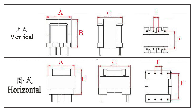
Type | Structure
Tурe | Dimension(mm) | Pin Row (mm) | Row Pitch(mm) | OD Pin(mm) | note | A | B | C | Pin | E | F | EE12-001 | Horizontal | 12.5 | 15.0 | 9.3 | 2+2 | 6.0 | 12.0 | SQ0.50*0.50 | 2 Slots/槽 | EE12.5-001 | Vertical | 13.0 | 12.5 | 9.0 | 5+5 | 2.5 | 7.5 | Φ0.60 |
| EE12.7-001 | Vertical | 12.8 | 12.3 | 11.0 | 5+5 | 2.5 | 8.5 | Φ0.60 |
|
* The above are the commonly used bobbin styles of the company.,Other styles are not included for the time being.,Welcome to consult. Our company can customize high - frequency transformers of various specifications according to customer requirements.
EE12 Transformer. The "EE" refers to the core structure formed by pairing two "E"-shaped cores, and the "12" indicates the side leg width of the core is 12mm. The EE12 is a highly classic, small-size, mid-to-high frequency power core widely used in consumer electronics, industrial control, communication equipment, and other fields, especially in switching power supplies requiring high power density and efficiency. I. Core Structural Characteristics
Core Material: Typically uses power ferrite materials such as PC40, PC44, PC47, etc., suitable for operating frequencies from tens of kHz to several hundred kHz.
Compact Size: Small volume, making it ideal for highly integrated circuit design.
Window Area: The window area (winding space) is relatively moderate for its size, but limited by its dimensions, the wire cross-sectional area and number of turns are constrained.
II. Detailed Explanation of Key Electrical Performance Parameters Electrical performance is closely related to the core's geometric dimensions, material properties, and winding process. The following are several core electrical performance aspects considered in EE12 transformer design: 1. Power Handling Capability 2. Inductance and AL Value
AL Value: This is the core's "inductance factor," typically measured in nH/N² (or µH/N²). It indicates the inductance generated per turn. It's key for calculating turns.
EE12 Typical AL Value: Varies greatly depending on core material and air gap size.
No Air Gap: Using a standard core pair without gap yields a high AL value, e.g., around 1000 nH/N² for PC40 material. This results in high magnetizing inductance but makes the core prone to saturation, suitable only for signal transformers or specific topologies.
With Air Gap: In flyback converters, an air gap is essential to prevent core saturation and store energy. Adding an air gap significantly reduces the AL value. For example, a typical EE12 flyback transformer might have an effective AL value in the range of 50 - 200 nH/N².
Design Calculation: The formula L = N² × AL can calculate the turns needed for a specified inductance, or estimate inductance from a given number of turns.
3. Saturation Flux Density and Maximum Ampere-Turns
Description: This is the core factor limiting the transformer's maximum power transfer. The core flux density (B) must not exceed the material's saturation flux density (Bsat, ~390mT at 100°C for PC40).
Design Limitation: According to Faraday's law of induction: V = N ⋅ Ae ⋅ (ΔB/Δt) ⋅ 10⁻⁸
Ae is the core's effective cross-sectional area (typical EE12 value ~13-15 mm², check specific model datasheet).
Given input voltage, on-time, and turns N, the flux density change ΔB can be calculated. It must be ensured that ΔB < Bsat, with a safety margin.
Ampere-Turns: Another perspective is that N ⋅ I_peak must not be too large. For a gapped core, the saturation current increases.
4. Losses and Temperature Rise
Copper Loss: I²R loss from the coil resistance when current flows. The EE12's small window limits wire gauge, making copper loss significant at high output currents, a major source of temperature rise. Multi-strand parallel winding or triple-insulated wire is often used for optimization.
Core Loss: Related to operating frequency, flux density swing (ΔB), and core material. At high frequencies, core loss (iron loss) becomes the primary concern. Higher-grade materials like PC44/PC47 have superior high-frequency loss characteristics compared to PC40.
Temperature Rise: The EE12's small volume and limited heat dissipation area can lead to high temperature rise when operating at full power and high frequency. Good winding practices (reducing leakage inductance, uniform winding) and system thermal design are crucial.
5. High-Frequency Characteristics and Parasitic Parameters
Leakage Inductance: Due to the EE12's small size, primary and secondary windings cannot couple perfectly, resulting in leakage inductance. This causes voltage spikes on the switching device and reduces efficiency. Interleaved (sandwich) winding of primary and secondary layers is used to minimize leakage inductance.
Distributed Capacitance: Capacitance exists between winding layers, turns, and primary-secondary, affecting high-frequency response and generating noise during switching. Winding design must balance the trade-off between leakage inductance and distributed capacitance.
III. Typical Applications and Design Considerations
Switching Mode Power Supplies (SMPS): This is the primary application area for EE12, especially flyback converters. They are ubiquitous in phone chargers, low-power adapters, and auxiliary power supplies.
Operating Frequency: Commonly found in the 60kHz - 150kHz range. With the development of fast-charging technology, many designs now operate above 100kHz, even reaching 200-300kHz, demanding higher-grade core materials (PC47 or better) and more precise winding techniques.
Design Key Points:
Define Requirements: Input/output voltage, power, efficiency, operating frequency, insulation requirements.
Calculate Parameters: Calculate primary inductance (Lp), peak current (Ipk), turns ratio (N) based on topology formulas.
Select Core: Can the EE12 meet the power requirement? Preliminary estimation can be done using the "Area Product (Ap)" method.
Calculate Turns: Calculate primary turns using Np = √(Lp/AL), then calculate secondary turns based on the turns ratio.
Verify Flux Density: Use Faraday's Law to verify ΔB, ensuring sufficient margin (operating ΔB is typically set between 0.1-0.2 T to avoid saturation and overheating).
Select Wire Gauge: Choose a wire gauge that fits within the window, meets copper loss requirements, based on current density (typically 4-8 A/mm²).
Characteristics of the EE12 Transformer We can summarize the key features of the EE12 transformer from three dimensions: structure, performance, and application. It is a crucial component playing a "small yet powerful" role in modern power electronics. Core Feature Overview The EE12 transformer is a small-sized, mid-to-high frequency, ferrite-core power transformer. All its characteristics revolve around the core objective of "efficiently achieving energy conversion and isolation within an extremely small space." I. Structural Characteristics II. Electrical Performance Characteristics
Excellent Mid-to-High Frequency Characteristics:
Utilizes high-frequency power ferrite materials (e.g., PC40, PC44). The optimal operating frequency typically ranges from tens of kHz to several hundred kHz (commonly 60kHz - 200kHz+), perfectly matching the high-frequency trend of modern switching power supplies to reduce the size of passive components.
High Power Density:
Within an extremely small volume (typically a few cubic centimeters), it can handle power from 5W to 25W (depending on frequency, topology, and cooling), offering outstanding power density.
High Electrical Isolation Capability:
The bobbin is designed with adequate creepage and clearance distances. A high isolation voltage (e.g., >3000VAC primary-secondary withstand voltage) can be applied between the primary and secondary windings, meeting safety standards and ensuring user safety.
Strong Design Dependency, Significant Parasitic Parameters:
Advantage: Highly flexible design. By adjusting turns, air gap, and winding methods, it can be adapted to various voltage and current requirements.
Challenges:
Leakage Inductance: Due to its small size and closely spaced windings, the primary-secondary coupling is not as strong as in larger transformers, resulting in relatively higher leakage inductance. Processes like "sandwich winding" must be employed to suppress this.
Thermal Management: The small volume means limited heat dissipation area. Temperature rise is a major limiting factor. Copper loss is significant during high current output, and core loss is high at elevated frequencies.
Distributed Capacitance: Inter-winding layer capacitance affects high-frequency performance and EMI.
III. Application and Market Characteristics
The EE12 transformer is a core magnetic component for low-power, high-frequency switching power supply isolation and energy conversion. Its applications are ubiquitous in virtually all fields requiring efficient, safe, and compact power supplies. A detailed classification of its specific application scenarios is provided below: I. Mainstream and High-Volume Applications This is the broadest and highest-quantity application area for EE12 transformers, driven primarily by cost, efficiency, and size. Consumer Electronics Power Adapters/Chargers Typical Power: 5W - 18W Specific Products: Mobile phone chargers, power supplies for wireless routers/set-top boxes, charging docks for smartwatches/bluetooth earphones, power modules for small appliances (e.g., electric toothbrushes, shavers). Function: Converts mains power (AC 85-265V) into safe, isolated low-voltage direct current (e.g., 5V, 9V, 12V). Its high-frequency characteristics (~60-100kHz) are key to the miniaturization of chargers. LED Lighting Drive Power Supplies Typical Power: 3W - 20W Specific Products: Isolated constant-current drive power supplies for LED bulbs, light tubes, downlights, and light strips. Function: Provides electrical isolation from the mains (ensuring safety) and converts the input voltage to a constant current suitable for the LED string. The size and cost advantages of the EE12 make it the preferred choice for mainstream LED drive solutions. Equipment Auxiliary Power/Standby Power Supplies Typical Power: 2W - 10W Specific Products: "Chip power supplies" inside large appliances such as TVs, washing machines, air conditioners, and industrial frequency converters. Function: Provides one or more sets of isolated, stable low voltages (e.g., 5V, 12V, 15V) for control systems (MCUs), sensors, relays, display panels, etc., whether the device is in operation or standby. This is a significant application of EE12 transformers in industrial control. Communication and Networking Equipment Typical Power: 10W - 25W Specific Products: Internal DC-DC isolated power modules for devices like optical modems, ONUs, switches, routers, and PoE splitters. Function: Isolates the input from internal circuits or generates the required operating voltages for different functional circuits. High reliability is a key feature of its application in this field. II. Special and Functional Applications In these applications, the EE12 transformer not only provides power but also serves specific electrical functions. Isolated DC-DC Converter Modules Converts one DC voltage (e.g., 24V, 48V) into another isolated DC voltage (e.g., 5V, ±12V). The EE12 is a commonly used core for building the "heart" of such modular power supplies. Sampling and Drive Isolation Current/Voltage Sampling Isolation: Used in motor drives, photovoltaic inverters, etc., to isolate and sample high-voltage side signals from the main circuit and transmit them to the low-voltage control side. Gate Drive Isolation: Provides an isolated power supply for the driving circuitry of MOSFETs/IGBTs, ensuring potential separation between the power devices and the control circuits. (In such high-frequency drive applications, EE12 transformers are commonly used as cores for drive transformers.) |


