* Product parameters
Operating frequency:10kHz-500KHz Operating temperature:-40℃ to +125℃ Storage temperature:-25℃ to +85℃ Storage humidity:30 to 95%
* Product features The features of the EE25 transformer stem fromthe physical dimensions of the EE25 magnetic core (52mm² Ae, 42mm² Aw) and the electrical properties of common ferrite materials such as PC40. Its core positioning is:A general - purpose solution that achieves the best balance among power, efficiency, cost, processability, and reliability.
* Typical application fields
* Product standards UL, RoHS, 3C, CQC
* Dimensions and specifications 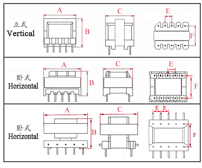
Type | Structure
Tурe | Dimension(mm) | Pin Row (mm) | Row Pitch(mm) | OD Pin(mm) | note | A | B | C | Pin | E | F | EE25-001 | Vertical | 26.0 | 17.2 | 22.0 | 4+4 | 5.0 | 12.0 | Φ0.80 |
| EE25-002 | Vertical | 26.0 | 20.5 | 22.0 | 5+5 | 5.0 | 15.0 | Φ0.80 |
| EE25-003 | Vertical | 26.0 | 25.0 | 15.6 | 5+5 | 5.00/6.00 | 22.0 | SQ0.64*0.64 | Double slots | EE25-004 | Horizontal | 26.0 | 20.5 | 17.5 | 4+4 | 4.0 | 15.0 | Φ0.80 |
| EE25-005 | Horizontal | 26.3 | 27.5 | 25.0 | 4+4 | 5.0 | 20.0 | Φ0.80 |
|
The above are the commonly used bobbin styles of the company,Other styles are not included for the time being,Welcome to consult. Our company can customize high - frequency transformers of various specifications according to customer requirements.
EE25 Transformer Electrical Performance Analysis The EE25 transformer (A=25mm) is a medium-to-high power high-frequency transformer. Compared to smaller/medium-sized models like EE16, EE19, and EE22, its core's effective cross-sectional area (Ae) and window area (Aw) are significantly increased, leading to substantial improvements in power handling capability, thermal stability, and electromagnetic compatibility. Its core electrical performance is determined by the magnetic core material, winding technology, topology scheme, and thermal design, making it suitable for 50–120W medium-to-high power supply scenarios. The following analysis covers core parameters, performance influencing factors, and optimization directions. I. Core Electrical Performance Parameters (Baseline Conditions: N87 Ferrite, 100kHz, Forward/LLC Topology) Parameter Category | Key Indicators | Typical Value / Range | Explanation | Basic Electromagnetic Parameters | Inductance (L) | 1mH–30mH | Determined by core AL value, number of turns, and air gap; tolerance ±2% to ±5%; wide air gap adjustment range, adaptable to multiple topologies. | Leakage Inductance (Lk) | 0.5%–1.5% of L | With identical winding technique, leakage inductance is much lower than smaller cores, reducing voltage spikes and EMI filter costs. | DC Resistance (DCR) | Primary: 0.1–2Ω; Secondary: 0.03–0.8Ω | Large window area allows for thicker wire gauges, significantly reducing copper loss. | Loss & Efficiency | Core Loss (Pc) | 300–800mW | Increases with frequency/flux density; N87 material reduces high-frequency loss by over 40% compared to PC44. | Copper Loss (Pcu) | 400–1200mW | Affected by current density/winding process; multi-strand Litz wire suppresses high-frequency skin effect. | Efficiency (η) | 92%–97% | Higher efficiency than EE25 at equivalent power; full-load efficiency in LLC topology can exceed 96%. | Safety & Insulation | Isolation Withstand Voltage | Primary-Secondary: 4–6kV AC/1min | Bobbin barrier height ≥8mm, creepage distance ≥6mm, meeting medical/industrial safety standard requirements. | Insulation Resistance | ≥1000MΩ (500VDC) | Excellent moisture resistance, suitable for high-humidity industrial/outdoor environments. | Thermal Performance & Endurance | Operating Frequency | 8kHz–500kHz | Very low saturation risk at low frequencies, controllable high-frequency loss, covering scenarios from power frequency critical points to high-frequency switching supplies. | Output Power | 50–120W | 80W with natural convection; up to 120W with forced air cooling or heatsink. | Operating Temperature | -40℃~+180℃ | Compatible with Class H (180℃) insulation system; full-load temperature rise ≤55℃. |
II. Key Factors Affecting Performance 1. Core Characteristics: The Core Support for Power and StabilityAdvantage of external span A=25 mm: Effective cross-sectional area (Ae) increases by approximately 50% compared to EE22, significantly enhancing flux handling capability and markedly reducing core saturation risk under high-current conditions. The increased window area (Aw) allows for accommodating more turns and/or thicker enameled wires, balancing design needs for high inductance and low copper loss. Air Gap Design: Optimal air gap range is 0.4–1.5mm.
Forward Topology: Requires a small and uniform air gap (0.4–0.8mm) to ensure core reset.
Flyback Topology: Air gap can be increased (1.0–1.5mm) to boost saturation current.
LLC Resonant Topology: Requires precise air gap control to ensure matching between magnetizing inductance and resonant capacitor parameters.
Material Selection:
N87: Suitable for high-frequency scenarios (80–500kHz), offering low loss, high permeability, and excellent high-temperature resistance. Preferred for industrial/automotive power supplies.
3C94: Suitable for 200–500kHz, offering balanced cost-effectiveness, ideal for medium-to high power consumer electronic adapters.
PC44: Suitable for 50–200kHz, lower cost, suitable for cost-sensitive, high-volume applications.
2. Winding Design: The Key to Loss Control Turns Ratio & Wire Gauge: The turns ratio determines the voltage conversion ratio. For 50–120W supplies, primary wire diameter is recommended at 0.5–1.0mm, secondary at 1.0–2.0mm. For high output current, the secondary uses multiple parallel strands (e.g., 3–5 strands of 0.6mm wire) to suppress skin effect. Winding Technique: Using interleaved winding (e.g., primary-secondary-primary-secondary) plus a copper foil shield can control leakage inductance to within 1% of the main inductance. Adding a double layer of polyimide tape between primary and secondary meets high isolation withstand voltage requirements. For high-frequency operation, use Litz wire with strand diameters of 0.1–0.2mm, reducing high-frequency copper loss by 30–40%. Insulation Design: Use Nomex insulation paper between layers. Primary-secondary creepage distance should be ≥6mm, meeting standards like UL60601 (medical-grade) and UL508 (industrial-grade), suitable for high-reliability scenarios. 3. Topology Matching: Core to Efficiency and Reliability
LLC Resonant Topology: Suitable for 80–120W high-efficiency power supplies, efficiency can exceed 96%. The low leakage inductance of EE25 reduces resonant loss and improves system stability, making it the preferred topology for laptop adapters and energy storage power supplies.
Forward Topology: Suitable for 50–80W low-ripple power supplies, requiring a reset winding or active clamp circuit. The large Ae reduces flux density, decreasing core loss, suitable for industrial control power supplies.
Flyback Topology: Suitable for 50–60W cost-sensitive solutions. Compared to EE22, it can use fewer turns and larger wire diameter, further reducing copper loss and enhancing overload capability.
4. Operating Conditions: Ensuring Long-term Stable Operation
Frequency: Core loss is proportional to the square of frequency. When frequency exceeds 300kHz, prioritize low-loss materials like N87 or 3C94. When frequency is below 20kHz, reduce flux density to avoid saturation.
Temperature: High temperature reduces permeability and increases losses. Ensure core operating temperature does not exceed the Curie temperature (~230℃ for N87). Using thermal adhesive to bond the core to an aluminum heatsink can reduce temperature rise by 15–20℃.
Load Rate: Optimal efficiency typically occurs at 75–90% load. Under light load (<20%), optimize winding distributed capacitance to reduce standby loss to below 50mW.
III. Performance Optimization Suggestions
Material Optimization: Use N87 instead of 3C94 for high-frequency scenarios; choose N97 for high-temperature industrial scenarios; PC44 can be used for cost-sensitive consumer electronics.
Winding Optimization: Mandate the use of Litz wire for frequencies ≥200kHz. Employ interleaved winding + double-layer copper foil shielding to control leakage inductance within 0.8%.
Thermal Optimization: Apply high-thermal conductivity silicone grease on the core surface and attach a heatsink. Design cooling air ducts in the power supply enclosure to improve forced air cooling efficiency.
Parameter Matching: For LLC topology, prioritize magnetizing inductance accuracy. For Forward topology, reduce the air gap and match reset winding parameters. For Flyback topology, increase the air gap to enhance saturation resistance.
EE25 Transformer Electrical Performance The EE25 transformer belongs to the medium-to-high power high-frequency transformer category. Compared to smaller/medium-sized models like the EE16, EE19, and EE22, its core's effective cross-sectional area (Ae) and window area (Aw) are significantly enlarged. This results in core performance characteristics of high-power handling capability, high efficiency with low loss, and high stability with strong compatibility, as detailed below: Broad Power Range, Robust Power Handling Capability
Output power can reach 50–80W under natural convection cooling. With a heatsink or forced air cooling, the upper power limit can be increased to 120W, representing an approximate 70% increase in power capacity compared to the EE22.
The larger Ae significantly reduces the risk of core saturation under high-current conditions, making it directly suitable for the power supply needs of medium-to-high power devices like laptop adapters and small energy storage power supplies.
Excellent High-Frequency Adaptability, Lower Losses & Higher Efficiency
Operating frequency range covers 8kHz to 500kHz. Saturation risk is extremely low at low frequencies. At high frequencies, when paired with low-loss materials like N87 or 3C94, core loss can be reduced by over 40% compared to PC44.
Overall efficiency reaches 92% to 97%, with full-load efficiency in LLC resonant topology even exceeding 96%.
Leakage inductance is only 0.5% to 1.5% of the main inductance, substantially reducing voltage spikes and EMI interference, and lowering the design difficulty of filter circuits.
Outstanding Insulation & Stability, Suitable for Demanding Conditions
Bobbin barrier height ≥8mm, primary-secondary creepage distance ≥6mm, with isolation withstand voltage up to 4–6kV AC for 1 minute, meeting UL60601 (medical-grade) and UL508 (industrial-grade) safety standard requirements.
Insulation resistance ≥1000MΩ (at 500VDC), featuring excellent moisture and corrosion resistance.
Capable of stable operation across a wide temperature range of -40℃ to +180℃, suitable for high-reliability scenarios like industrial, automotive, and outdoor applications.
Strong Topology Compatibility, High Design Flexibility
Perfectly compatible with mainstream topologies like LLC Resonant, Forward, and Flyback:
LLC topology suits 80–120W high-efficiency power supplies.
Forward topology fits 50–80W applications requiring low ripple.
Flyback topology enables 50–60W cost-effective solutions.
By adjusting the air gap within 0.4–1.5mm, inductance and saturation current can be precisely controlled to meet the parameter requirements of different topologies.
Ample Winding Design Space, Precise Loss Control
The extra-large window area allows for the use of thicker enameled wires (secondary wire diameter can reach 1.0–2.0mm) or multiple parallel strands. This significantly reduces DC resistance (DCR) and copper loss.
For high-frequency operation, pairing with Litz wire can effectively suppress skin and proximity effects, reducing high-frequency copper loss by 30–40%.
The technique of interleaved winding + copper foil shielding can further compress leakage inductance to below 1%.
Mature Manufacturing Process, Balanced Cost-Effectiveness
As a standardized medium-to-high power core model, it benefits from a mature supply chain for molds and bobbins, ensuring controllable mass production costs.
Compared to larger transformers like the EE28 and EE30, the EE25 meets medium-to-high power requirements while balancing compact size and cost advantages, making it a cost-effective choice for the 50–120W power range.
Clear Limitations
When power exceeds 120W, core loss and copper loss increase sharply, making temperature rise difficult to control, necessitating a switch to a larger core size.
Not suitable for power frequency (50/60Hz) power supply applications, as core loss at low frequencies is excessively high, resulting in extremely poor energy efficiency.
Typical Application Scenarios of EE25 Transformer Leveraging its medium-to-high power capacity and excellent stability, the EE25 transformer is widely used in the following fields:
Consumer Electronics: 65–100W laptop adapters, 20V/5A fast-charging power supplies, small energy storage power supplies (e.g., 100W portable power stations), balancing efficiency, size, and cost.
Industrial Control: High-power PLC module power supplies, servo drive main power supplies, auxiliary power supplies for industrial frequency converters, meeting the requirements for wide-temperature (-40℃~+180℃) operation and high insulation in industrial environments.
LED Commercial Lighting: 80–120W LED industrial and mining lights, commercial spotlights, and outdoor streetlight driver power supplies, supporting a high power factor (PF≥0.97) and low harmonic distortion (THD≤8%), in compliance with energy efficiency standards.
Medical Electronics: Isolated power supplies for medium-sized medical equipment (e.g., portable ultrasound diagnostic devices, blood centrifuges), meeting medical-grade safety standards, with low leakage current design ensuring usage safety.
Automotive/Energy Storage Electronics: 100W automotive inverters, small RV power supply modules, and auxiliary power supplies for energy storage battery management systems (BMS), suitable for the demanding automotive environment characterized by vibration and wide temperature ranges.
|


