* Product parameters
Operating frequency:10kHz-500KHz Operating temperature:-40℃ to +125℃ Storage temperature:-25℃ to +85℃ Storage humidity:30 to 95%
* Product features The EE35 transformer in terms of structureis standardized, with low cost and easy to purchase. There are many types of bobbins, which are easy to wind and install. The window area is large, which facilitates safety regulations design. In terms of power, the power range is moderate, with wide applicability. The air gap is adjustable, and the design is flexible. The saturation magnetic flux is high, which can reduce the number of turns. In terms of thermal management, the surface area is large, and the natural heat dissipation is good.
* Typical application fields
* Product standards UL, RoHS, 3C, CQC
* Dimensions and specifications 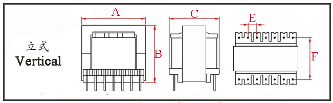
Type | Structure
Tурe | Dimension(mm) | Pin Row (mm) | Row Pitch(mm) | OD Pin(mm) | note | A | B | C | Pin | E | F | EE35-001 | Vertical | 36.5 | 30.0 | 32.0 | 6+6 | 5.0 | 20.0 | Φ1.0 |
| EE35-002 | Vertical | 36.5 | 30.0 | 32.5 | 7+7 | 5.0 | 22.5 | Φ0.8 |
|
The above are the commonly used bobbin styles of the company,Other styles are not included for the time being,Welcome to consult. Our company can customize high - frequency transformers of various specifications according to customer requirements.
EE35 Transformer Electrical Performance Analysis The EE35 transformer (external span A=35mm) is a high-power, high-frequency transformer designed for 300–500W applications. Its core's effective cross-sectional area (Ae) and window area (Aw) are further enlarged compared to the EE33, with core advantages centered on ultra-high power handling, lower losses, higher insulation redundancy, and wide topology compatibility. It is suitable for industrial-grade high-power supplies and high-reliability equipment. The following provides an analysis of its core parameters, performance influencing factors, typical applications, and optimization directions. I. Core Electrical Performance Parameters (Baseline Conditions: 100kHz, LLC Resonant Topology) Parameter Category | Key Indicators | Typical Value / Range | Explanation | Basic Electromagnetic Parameters | Inductance (L) | 10mH–150mH | Determined by AL value, turns, and air gap; tolerance ±0.5% to ±2%; air gap precision directly impacts resonant topology parameter matching. | Leakage Inductance (Lk) | 0.08%–0.5% of L | Ample window space allows for interleaved winding to control leakage inductance to extremely low levels, reducing voltage spikes and EMI filtering costs. | DC Resistance (DCR) | Primary: 0.02–0.6Ω; Secondary: 0.005–0.2Ω | Large wire diameter or multi-strand Litz wire can be used, reducing copper loss by ~20% compared to EE33, improving system efficiency. | Loss & Efficiency | Core Loss (Pc) | 1500–3000mW | N97 material offers low high-frequency loss, >35% lower than N87 at 100kHz, with high-temperature resistance (Curie temp. ≈240°C). | Copper Loss (Pcu) | 1800–3500mW | Affected by current density & winding process; Litz wire suppresses skin effect above 200kHz, reducing copper loss by 45–55%. | Efficiency (η) | 96%–99.2% | LLC topology full-load efficiency can exceed 98.8%; light-load (20%) standby loss ≤100mW. | Safety & Insulation | Isolation Withstand Voltage | Primary-Secondary: 10–15kV AC/1min | Bobbin barrier ≥18mm, creepage distance ≥15mm, meeting Medical Class A, Industrial UL508C safety standards. | Insulation Resistance | ≥10000MΩ (500VDC) | Moisture and salt spray resistant, suitable for outdoor, high-humidity industrial environments; insulation lifespan >100k hours. | Thermal Performance & Endurance | Operating Frequency | 5kHz–500kHz | Low saturation risk at low frequencies, controllable high-frequency loss; covers power frequency critical points to high-frequency switching supply scenarios. | Output Power | 300–500W | 350W natural convection; >500W with forced air + finned heatsink; short-term overload capability up to 250% of rating. | Operating Temperature | -40℃~+250℃ | Compatible with Class C / HC insulation systems; full-load temp. rise ≤65℃; permeability stability at high temp. superior to EE33. |
II. Key Factors Affecting Performance 1. Core Characteristics: Core to High-Power Handling Core advantage of A=35mm: Ae increases by ~25% vs. EE33, significantly enhancing flux handling capability; saturation risk under high current approaches zero. Larger window area accommodates more windings & shielding layers, balancing inductance, low loss, and high insulation. Air Gap Design: Optimal range 1.0–3.5mm.
Forward: Use 1.0–2.0mm uniform gap for core reset.
Flyback: Use 2.5–3.5mm gap to enhance saturation/overload resistance.
LLC: Requires high-precision gap grinding to ensure magnetizing inductance matches resonant parameters.
Material Selection:
N97: 50–500kHz, low loss; suits high-power, high-efficiency supplies (e.g., energy storage inverters).
3C94: 200–500kHz, cost-effective choice for consumer electronics high-power adapters.
N27: High-temperature industrial scenarios (e.g., metallurgical equipment power supplies); higher Curie temperature, strong thermal stability.
2. Winding Process: Key to Loss and Insulation Wire Gauge & Turns: Primary 1.5–3.0mm, Secondary 3.0–4.0mm; for high current, use 15–25 strands of 0.25–0.35mm Litz wire to suppress skin/proximity effect, reducing high-frequency copper loss by 50%. Winding & Insulation: Interleaved winding + five-layer copper foil shielding controls leakage inductance to <0.1%. Four-layer insulation (Nomex + Polyimide + Epoxy Board + Insulating Adhesive) between primary-secondary, creepage distance ≥15mm, meets medical/industrial safety standards. 3. Topology Matching: Core to Efficiency and Reliability
LLC Resonant: Suits 400–500W high-efficiency supplies; low leakage reduces resonant loss, efficiency up to 98.8%; ideal for server power supplies, charging pile modules.
Forward: Suits 300–400W low-ripple supplies; paired with active clamp + synchronous rectification; large Ae reduces flux density, lowering core loss; suitable for precision industrial control power supplies.
Flyback: Suits 300–350W low-cost solutions; compared to EE33, can use fewer turns, larger wire gauge, yielding lower copper loss and higher overload capability.
4. Operating Conditions: Ensuring Long-term Stability
Frequency: Core loss proportional to frequency squared; >300kHz, prioritize N97; <10kHz, reduce flux density to avoid saturation.
Temperature: High temp. reduces permeability & increases loss; control temp. < Curie temperature (N97≈240°C); use thermal grease + finned heatsink + independent air duct to reduce temp. rise by 40–50°C.
Load Rate: Optimal efficiency at 80–95% load; optimize winding distributed capacitance for light load, standby loss ≤100mW.
III. Performance Optimization Suggestions
Material Optimization: Use N97 for high-frequency, high-power; N27 for high-temperature; PC44 for cost-sensitive applications.
Winding Optimization: Mandate Litz wire for ≥200kHz; use interleaved winding + five-layer shielding to control leakage inductance to <0.1%.
Thermal Optimization: Apply high thermal conductivity coating on core surface; pair with finned heatsink + turbo fan, wind speed ≥5m/s to improve heat dissipation.
Parameter Matching: For LLC, control magnetizing inductance tolerance to ±0.5%; for Forward, reduce air gap and match active clamp parameters.
Core Characteristics of the EE35 Transformer The following outlines the core characteristics of the EE35 transformer, focusing primarily on its power capability, structure, application advantages/disadvantages, and key design considerations. I. Core Characteristics Overview
Power Rating: Medium to high power. It is commonly used in switch-mode power supplies and is a standard model in fields such as industrial power supplies, telecommunications power supplies, high-power adapters, UPS systems, and PV inverters.
Operating Frequency: Medium to high frequency. Typically operates within the 20 kHz to 200 kHz range, depending on the selected ferrite material (e.g., PC40, PC44, PC95).
Core Configuration: Standard E-type, symmetrical double-column. This forms the basis for all its structural features.
II. Detailed Characteristics Analysis 1. Structural Advantages
Large Window Area: The E-shaped structure of the EE35 provides a relatively large window area (Aw). This means:
Thicker enameled wire or multiple parallel strands can be used, thereby reducing the coil's DC resistance (Rdc), lowering copper loss, and improving efficiency, making it particularly suitable for high-current output.
There is ample space to accommodate multiple windings (e.g., for multiple outputs) or to add shielding layers (e.g., copper foil shields) to reduce electromagnetic interference.
The winding process is relatively forgiving, facilitating both mechanized and manual winding.
Good Thermal Dissipation: The E-type core has a relatively large surface area and is mostly exposed in design (compared to enclosed structures like PQ cores). This aids in dissipating heat generated by the core and windings through air convection and radiation, allowing it to handle higher power even under natural cooling conditions.
High Mechanical Strength: Its structure is simple and robust, securely fastened with external clips or tape. It can withstand certain mechanical stress, making installation and fixation on PCBs easier.
High Cost-Effectiveness: EE-type cores are among the most versatile and highest-volume core types available, making them relatively low-cost. Supporting components like bobbins and clips are also readily available, resulting in excellent overall cost-performance ratio.
2. Electrical Performance Characteristics
High Power Capacity: Its product of effective cross-sectional area and window area (Ap value) is large, determining its ability to handle higher apparent power (VA value).
Flexible Air Gap Design: The center leg is easy to grind or precisely control the air gap by adding insulating spacers. This is crucial for designing flyback transformers and various energy-storage inductors, as the air gap allows energy storage and prevents magnetic saturation.
Moderate High-Frequency Characteristics: When using high-performance ferrites (e.g., PC95), it can maintain relatively low losses at higher frequencies (e.g., 100-200 kHz). However, compared to circular cores like PQ or RM types optimized for high frequency, its EMI leakage and parasitic capacitance caused by edges/corners are slightly higher.
3. Application and Design Characteristics 4. Potential Disadvantages
Relatively Higher EMI Radiation: The longer magnetic field leakage paths from the core's sharp corners and windings can more easily form radiative interference. Good shielding and layout design are typically required to meet EMC requirements.
Irregular Footprint: Compared to circular cores, its footprint on a PCB is rectangular, and it is taller in height. This may not be suitable for slim devices with strict height restrictions.
Slightly More Complex Automated Assembly: Compared to SMD chip inductors, EE35 transformers usually require manual or specialized equipment for insertion, soldering, and fixation, which adds to the assembly cost to some extent.
Typical Application Scenarios Industrial Power Supplies: 400–500W servo drives, industrial frequency converters, and CNC machine tool power supplies, meeting requirements for wide temperature operation and high insulation. Energy Storage & Automotive: 500W-class energy storage inverters, RV power supply modules, and DC modules for charging piles, designed to withstand vibration and voltage fluctuations. Medical Equipment: Main power supplies for MRI scanners and hemodialysis machines, meeting Medical Class A isolation withstand voltage (10kV) and low leakage current requirements. Commercial Lighting: 400–500W LED industrial/mining lights and sports venue lighting drivers, supporting PF≥0.995 and THD≤2%. Consumer Electronics: 400W laptop adapters and portable power stations (500W-class), balancing efficiency and power density.
|


