* Product parameters
Operating frequency:10kHz-500KHz Operating temperature:-40℃ to +125℃ Storage temperature:-25℃ to +85℃ Storage humidity:30 to 95%
* Product features The EE42 transformer isa common choice in medium - and high - power switching power supplies due to its good high - frequency characteristics, moderate power range, and mature standardized design.In actual design, optimization should be carried out in combination with specific topology, frequency, insulation level and other requirements, and attention should be paid to heat dissipation and EMC issues.
* Typical application fields Switching power supplies (SMPS): Such as server power supplies, industrial power supplies, and communication power supplies. Inverters and photovoltaic systems: DC - DC conversion stage. High - frequency isolation power supplies: Used in electric vehicle charging modules, UPS, etc. Inductive devices: Such as PFC boost inductors and resonant inductors
* Product standards UL, RoHS, 3C, CQC
* Dimensions and specifications 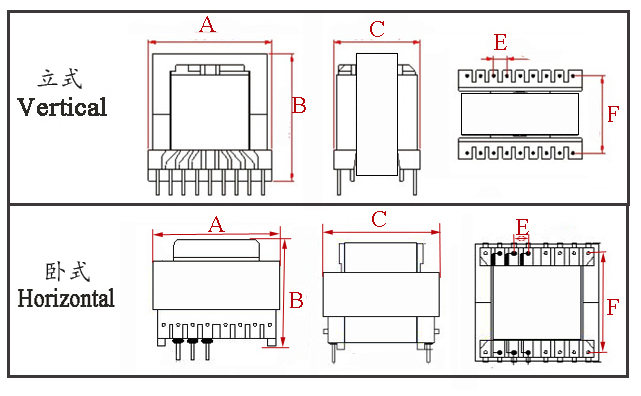
Type | Structure
Tурe | Dimension(mm) | Pin Row (mm) | Row Pitch(mm) | OD Pin(mm) | note | A | B | C | Pin | E | F | EE42-001 | Vertical | 43.5 | 40.0 | 45.0 | 6+6 | 5.0 | 32.5 | Φ1.0 |
| EE42-002 | Vertical | 46.5 | 33.0 | 47.0 | 8+8 | 5.0 | 28.0 | Φ1.0 |
| EE42-003 | Vertical | 46.5 | 38.0 | 48.0 | 9+9 | 5.0 | 27.5 | Φ1.0 |
| EE42-004 | Horizontal | 47.0 | 44.0 | 34.5 | 5+5 | 5.0 | 34.7 | Φ1.2 |
| EE42-005 | Horizontal | 43.0 | 44.0 | 40.0 | 6+6 | 7.4 | 33.0 | Φ1.0 |
| EE42-006 | Horizontal | 43.5 | 44.0 | 40.0 | 8+8 | 5.0 | 34.5 | Φ1.0 |
|
* The above are the common bobbin styles of the company,Other styles are not included for the time being,Welcome to consult. Our company can customize high - frequency transformers of various specificationsaccording to customer requirements.
EE42 Transformer Electrical Performance Explanation The EE42 transformer (external span A=42mm) is a 600–1200W medium-to-high-power high-frequency transformer. It is characterized by high power density, low loss, and strong insulation & thermal stability at its core, making it suitable for multiple topologies and complex operating conditions. The following details its key electrical performance dimensions. I. Baseline Core Electrical Parameters Parameter | Typical Value | Remarks | Rated Power | Natural Convection: 600–800W; Forced Air Cooling: 1000–1200W | ~20% increase compared to EE40 | Operating Frequency | 20kHz–500kHz | Compatible with mainstream switching power supply topologies | Core Material | PC44 / N97 Ferrite | High-frequency low loss, Bs ≈400–450mT | Isolation Withstand Voltage | Primary-Secondary: 15–20kV AC/1min; Winding-Core: 1.5kV AC/1min | Meets UL60601 / UL508C | Insulation Resistance | ≥10⁴ MΩ (500VDC) | Moisture & salt spray resistant; suitable for outdoor/industrial use | Efficiency | 97%–99% (LLC full-load); 95%–97% (Forward / Flyback) | Low-loss design | Leakage Inductance | 0.1%–0.3% of Inductance | Can be reduced to 0.05% with interleaved winding + shielding | Operating Temperature | -40℃~+125℃ (Winding); Core ≤ +150℃ | Wide temperature stability |
II. Detailed Explanation of Key Electrical Performance Power & Thermal Performance: High-Power Handling + Low Loss / Low Heat
The effective cross-sectional area (Aₑ) is ~12% larger, and the window area is ~10% larger than the EE40, supporting larger wire diameter (secondary 3.8–5.2mm) or multi-strand Litz wire, reducing copper loss.
Rated at 600W with natural convection and 1200W with forced air cooling; short-term overload capability 200%–300%.
Low core loss (e.g., ~200mW/cm³ for N97 @100kHz/200mT), combined with Class B insulation, results in a temperature rise ≤40K (at full load), suitable for long-duration operation in industrial/medical applications.
Insulation & Isolation: Top-Tier Safety + Strong Interference Immunity
Bobbin barrier ≥28mm, creepage distance ≥22mm, isolation withstand voltage 15–20kV, meeting Medical Class A / Heavy-Duty Industrial equipment insulation requirements. Leakage current ≤10μA ensures personnel and equipment safety.
High insulation resistance and low distributed capacitance suppress common-mode interference, simplify EMI filtering, and adapt to high-interference environments like variable frequency drives and servo systems.
Electromagnetic Performance: Low Leakage + High Coupling + Stable Parameters
Symmetrical magnetic path design provides a coupling coefficient ≥0.995 and very low leakage inductance, reducing voltage spikes, lowering stress on freewheeling diodes, and improving system reliability.
Inductance accuracy ±10%–±15%, low DCR (primary ≤300mΩ, secondary ≤50mΩ), and load regulation ≤1%, ensuring stable output.
Topology Compatibility: Fully Compatible + Highly Flexible
LLC Resonant: Suitable for 800–1200W high-efficiency power supplies. ZVS/ZCS reduces switching losses, enabling efficiency above 99%.
Forward / Flyback: Suitable for 600–800W applications. Low leakage inductance adapts well to active clamp circuits, reducing voltage stress.
Half-Bridge / Full-Bridge: Suitable for 1000–1200W industrial power supplies. The large window area supports multiple output windings, satisfying multi-rail power needs.
III. Performance Boundaries & Optimization Points Boundaries:
When power exceeds 1200W, core and copper losses increase significantly, and temperature rise becomes difficult to control. It is recommended to select EE45/EE50.
Not suitable for power frequency (50/60Hz) applications due to high losses.
Optimization:
Winding: Use primary sandwich + secondary layer, interleaved winding to reduce leakage inductance; employ copper foil shielding to suppress EMI.
Heat Dissipation: Forced air / water cooling can increase power handling by 30%–50%; applying thermal grease to the core reduces thermal resistance.
Magnetic Circuit: Use an air gap of 1.8–4.2mm to precisely control inductance and saturation current, adapting to different topologies.
IV. Typical Application Matching
Industrial: 800–1200W frequency converters, servo drives, CNC machine tool power supplies - featuring interference immunity, wide temperature range, and high reliability.
Energy Storage / Charging: 1000W energy storage inverters, DC charging pile modules - featuring high efficiency for extended runtime and vibration resistance.
Medical: Main power supplies for CT / MRI / dialysis machines - featuring top-tier safety standards and low leakage current, ensuring patient and staff safety.
Lighting / Display: 1000W LED venue lighting, outdoor large-screen power supplies - featuring high PF (≥0.99) and low THD (≤1%), meeting energy-saving compliance.
EE42 Transformer The EE42 transformer is a common ferrite core transformer used in electronic circuits. Its name derives from the size specification of the EE-type core it uses. The "42" in EE42 typically indicates that the length of the core is approximately 42mm (specific dimensions may vary slightly by manufacturer). The following are the main characteristics of the EE42 transformer: Main Characteristics Core Material and Structure
Material: Typically made of ferrite, offering advantages such as high permeability, low loss, and good high-frequency performance.
Structure: Composed of two "E"-shaped cores assembled together. An air gap can be optionally left between them to facilitate inductance adjustment. The coil is wound on the center leg. The structure is symmetrical, providing relatively good heat dissipation and mechanical stability.
Excellent High-Frequency Performance
Suitable for high-frequency switching power supplies ranging from kHz to several hundred kHz (e.g., flyback, forward, half-bridge topologies). It effectively reduces transformer size and increases power density.
Moderate Power Capacity
The EE42 size belongs to the medium-sized core category. It can typically handle power in the range of several hundred watts to around 1kW (specific value depends on topology, frequency, and heat dissipation conditions).
Flexible Air Gap Design Convenient Winding and Installation
EE42 Transformer Application Guide The EE42 transformer targets 600–1200W high-frequency, high-power scenarios, leveraging its advantages of high power density, low loss, high insulation, and wide-temperature stability. It has achieved widespread application in fields such as industry, energy storage, medical, and new energy, with specific details as follows: Key Application Matching Points
Power and Thermal Dissipation Matching: Suitable for 600–800W with natural convection and 1000–1200W with forced air cooling. For applications exceeding 1200W, it is recommended to select EE45/EE50 to avoid a sharp rise in core and copper losses.
Topology Preference: The LLC resonant topology is suitable for 800–1200W high-efficiency scenarios; Forward/Flyback topologies suit 600–800W low-ripple requirements; the Full-Bridge topology is suitable for high-power power supplies above 1000W.
Safety and Insulation: Medical/industrial equipment require enhanced creepage distance (≥22mm) and isolation withstand voltage (15–20kV). Communication equipment require leakage inductance control (≤0.1%) to suppress common-mode interference.
Winding Optimization: Use 3.8–5.2mm large-diameter wire or multi-strand Litz wire for the secondary to reduce copper loss. Employ interleaved layered winding and copper foil shielding to further minimize leakage inductance and EMI.
Application Boundaries and Selection Recommendations
Unsuitable Scenarios: Power frequency (50/60Hz) power supplies (due to high losses) and low-power (<500W) equipment (where it offers no advantage in size or cost).
Selection Recommendations: Choose the cooling solution based on power requirements. For high-frequency applications, prioritize pairing with low-loss cores such as N97/PC44. For safety-critical applications, enhance insulation design and leakage current testing.
|


